Magnetized pulsar ring, and rolling bearing device with sensor using the same

a technology of magnetic pulsar and sensor, which is applied in the direction of mechanical equipment, instruments, transportation and packaging, etc., can solve the problems of high brittleness, prone to damage, and deterioration of magnetic properties, so as to reduce the difference in deformation amount, reliably prevent the slip-out of the magnetized element, and reduce the stress generated in the magnetized element

Inactive Publication Date: 2010-10-12
JTEKT CORP
View PDF7 Cites 6 Cited by
  • Summary
  • Abstract
  • Description
  • Claims
  • Application Information

AI Technical Summary

Benefits of technology

[0016]The invention has been made in view of such circumstances. It is therefore an object of the invention to provide a magnetized pulsar ring and a rolling bearing device with a sensor using the same, capable of preventing damage caused by a temperature change, and suppressing deterioration of magnetic properties caused by wear or the like of a magnetized surface.
[0017]Another object of the invention is to provide a magnetized pulsar ring that uses a resin bonded magnet as a magnetized element to increase scratch resistance, and that improves thermal shock resistance and ensures fixation of the magnetized element in a case where the resin bonded magnet is used.

Problems solved by technology

In the rolling bearing device with a sensor in the above conventional example, there is a case that the magnetized pulsar ring is weak in strength because it is formed of a magnetic material using an elastic body, such as rubber, damage or wear is caused in the magnetized surface of the magnetized pulsar ring due to dust or the like penetrated from the outside, and magnetic properties deteriorate.
Further, the plastic magnet has excellent scratch resistance or wear resistance, as compared with the elastic body, such as rubber, whereas it has high brittleness, and is apt to be damaged by deformation.
Also, if an excessive deformation stress acts on the magnetized pulsar ring, there is a fear that the magnetized pulsar ring may be damaged.
In the above magnetized pulsar ring, the magnetized element that is formed as magnetic powder that has rubber as a binder may be damaged due to foreign matters.
However, in a case where the resin bonded magnet is used, the magnet is apt to be split because it is relatively weak in thermal shock and fixation of the magnetized element to the supporting member is difficult.

Method used


Image

  • Magnetized pulsar ring, and rolling bearing device with sensor using the same
  • Magnetized pulsar ring, and rolling bearing device with sensor using the same
  • Magnetized pulsar ring, and rolling bearing device with sensor using the same

Examples


first embodiment

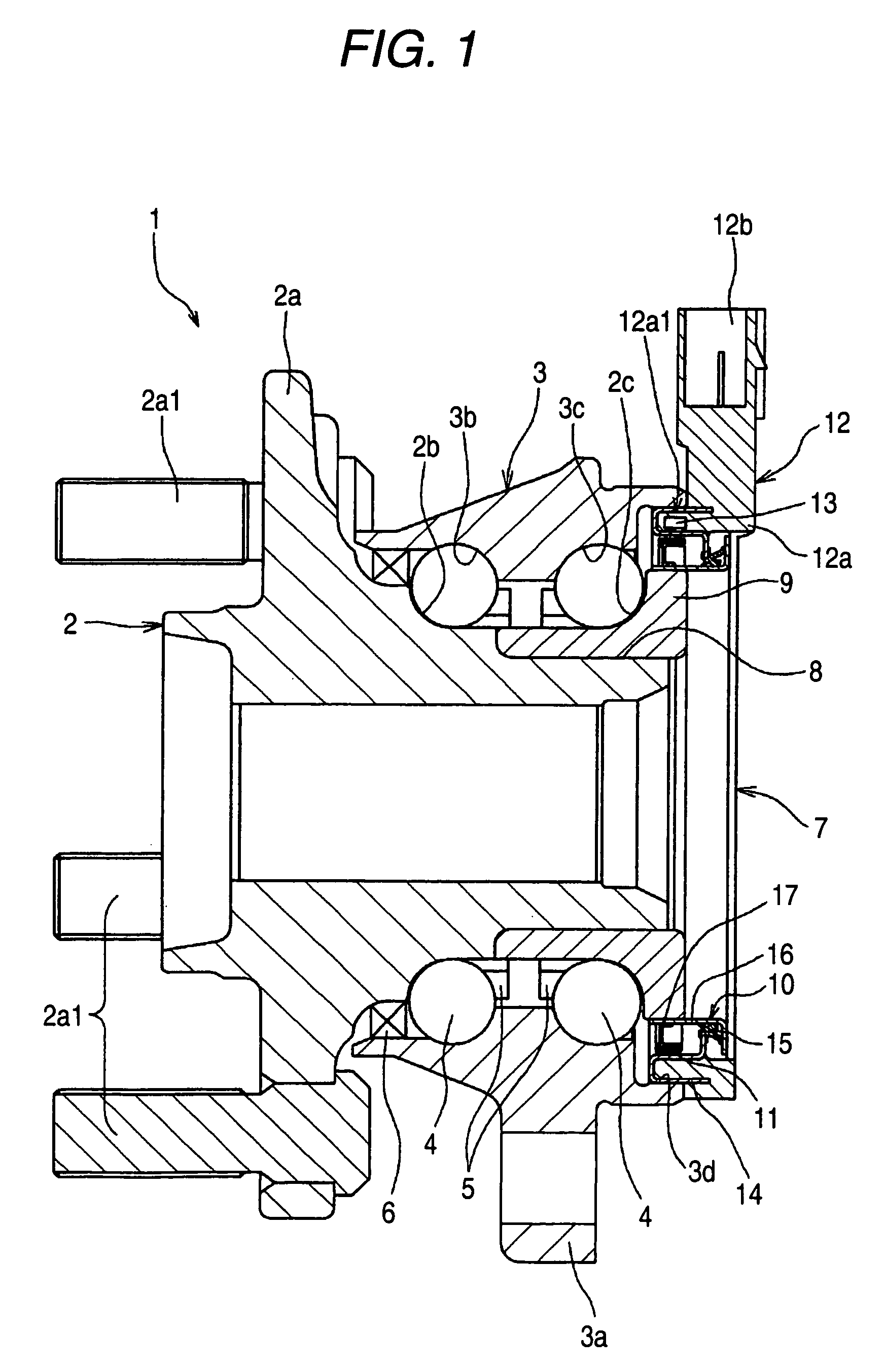
[0065]Next, preferable embodiments of the invention will be explained referring to the accompanying drawings. FIG. 1 is a sectional view showing the configuration of a rolling bearing device with a sensor including a magnetized pulsar ring according to a first embodiment of the invention. This rolling bearing device 1 with a sensor rotatably supports wheels of a vehicle, such as an automobile, to a suspension system.

[0066]Referring to FIG. 1, the rolling bearding device 1 with a sensor constitutes a plurality of rows of angular ball bearings, and includes an inner shaft 2 that has a flange portion 2a to which a wheel (not shown) is to be attached at its one end, an outer ring 3 arranged concentrically at an outer periphery of the inner shaft 2, a plurality of balls 4 serving as rolling elements that are interposed between the inner shaft 2 and the outer ring 3, and a cage 5 that holds these balls 4 at equal intervals in a peripheral direction. Further, the rolling bearing device 1 w...

second embodiment

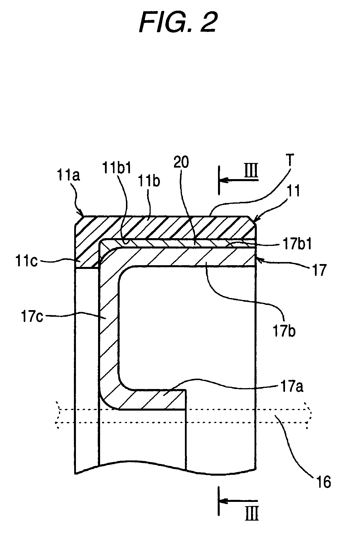
[0102]FIG. 6 is a sectional view of a magnetized pulsar ring 11 according to a second embodiment of the invention. The main difference between this embodiment and the first embodiment is that the ring body 11a is insert-molded in the shape of covering the supporting member 17, and instead of the ridges, protruding portions 21 that protrude axially, and prevents any rotation relative to the supporting member 17 is provided on the ring body 11a. Since other configurations of the second embodiment are the same as those of the first embodiment, the description thereof is omitted.

[0103]As described above, the ring body 11a of this embodiment is formed in a U-shape in cross section so as to cover the outer tubular portion 17b of the supporting member 17 by so-called insert molding, and has the tubular portion 11b located at the outer peripheral surface of the outer tubular portion 17b of the supporting member 17, the edge 11c extending radially inward along the annular portion 17c from on...

third embodiment

[0116]Third embodiment of the invention will be described. In the following description, right and left are defined as the right and left of FIG. 10 and respective drawings corresponding thereto.

[0117]FIGS. 10 and 11 show a third embodiment of a magnetized pulsar ring according to the invention.

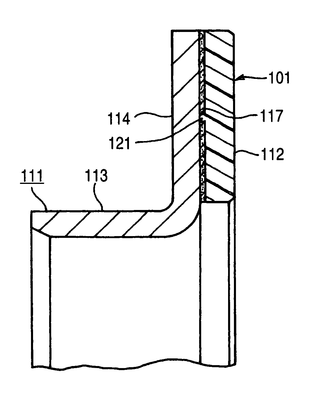
[0118]Referring to FIG. 10, a magnetized pulsar ring 101 includes a supporting member 111 fixed to the inner ring, and a magnetized element 112 provided in the supporting member 111.

[0119]The supporting member 111 includes a cylindrical portion 113 fitted to an outer periphery of the inner ring, and an outward flange portion 114 provided at a right end of the cylindrical portion 113.

[0120]The magnetized element 112 is a resin bonded magnet, and is fixed to the whole periphery of a right surface of the flange portion 114 of the supporting member 111 via an adhesive layer 117.

[0121]The adhesive layer 117 absorbs the difference between the deformation amount of the magnetized element 112, and th...


PUM


Abstract

A magnetized pulsar ring of the invention is a pulsar ring fixed to an outer peripheral surface of a supporting member and including a ring body in which a number of magnetic poles are at predetermined intervals in a peripheral direction. The ring body 11a is formed of a plastic magnet, and has a cushion member made of an elastic body that is interposed between the ring body and the outer peripheral surface.

Description

BACKGROUND OF THE INVENTION[0001]The present invention relates to a magnetized pulsar ring used for detection of the rotational frequency, etc. of a rotary body, and a rolling bearing device with a sensor using the magnetized pulsar ring.[0002]In a rolling bearing device that supports a wheel of an automobile, etc., a sensor for detecting the rotation speed of the wheel is built in order to control an anti-lock brake system, etc. Such a conventional rolling bearing device with a sensor has a magnetized pulsar ring set at an inner shaft (rotating ring), and a magnetic sensor that faces the magnetized pulsar ring, as described in the following JP-A-2006-220270, for example. The above magnetized pulsar ring is attached to the rotating ring so as to be integrally rotatable therewith by mixing magnetic powder, such as ferrite, into an elastic member composed of rubber, etc., and by vulcanizing and adhering the elastic member to an axial outside surface of a rotating-ring-side member (sli...

Claims


Application Information

Patent Timeline
Patent Type & Authority Patents(United States)
IPC IPC(8): G01B7/30
CPCF16C33/78F16C41/007F16J15/326G01P3/443G01P3/487F16C2326/02F16C19/186
Inventor ISHII, YASUHIKONUMATA, TETSUAKIMORIMURA, NAOKIMOTOHASHI, NOBUTSUNASHIGE, YOSHIFUMI
Owner JTEKT CORP
Why Eureka
Try Eureka