
RFID system and method for localizing and tracking a moving object with an RFID tag

a technology of radio frequency identification and tracking method, which is applied in the direction of electrical signalling details, burglar alarm mechanical actuation, instruments, etc., can solve the problems of complex readers employing intensive signal processing, difficult to implement the remaining two tasks, and inability to accurately locate and track objects. , to achieve the effect of accurate positioning and tracking

Inactive Publication Date: 2010-10-12
DJURIC PETAR M +1
View PDF16 Cites 36 Cited by
  • Summary
  • Abstract
  • Description
  • Claims
  • Application Information

AI Technical Summary

Benefits of technology

This system enables accurate localization and tracking of RFID tags by using sensor-tags to detect and decode responses from RFID tags, reducing errors and costs associated with complex signal processing, and improving range determination in indoor environments.

Problems solved by technology

Current RFID systems can perform the task of object detection and identification but have difficulty with the remaining two tasks.
However, implementation of these methods in RFID systems is extremely costly.
Such systems require complex readers employing intensive signal processing and need for multiple antenna arrays.
Additionally, for a typical RFID system the small distances between the reader and the tags cause difficulty in determining the range of the tag.
The presence of multipath in indoor environments where RFID systems are most commonly used also causes errors in the calculation of the range.

Method used


Image

  • RFID system and method for localizing and tracking a moving object with an RFID tag
  • RFID system and method for localizing and tracking a moving object with an RFID tag
  • RFID system and method for localizing and tracking a moving object with an RFID tag

Examples


Embodiment Construction

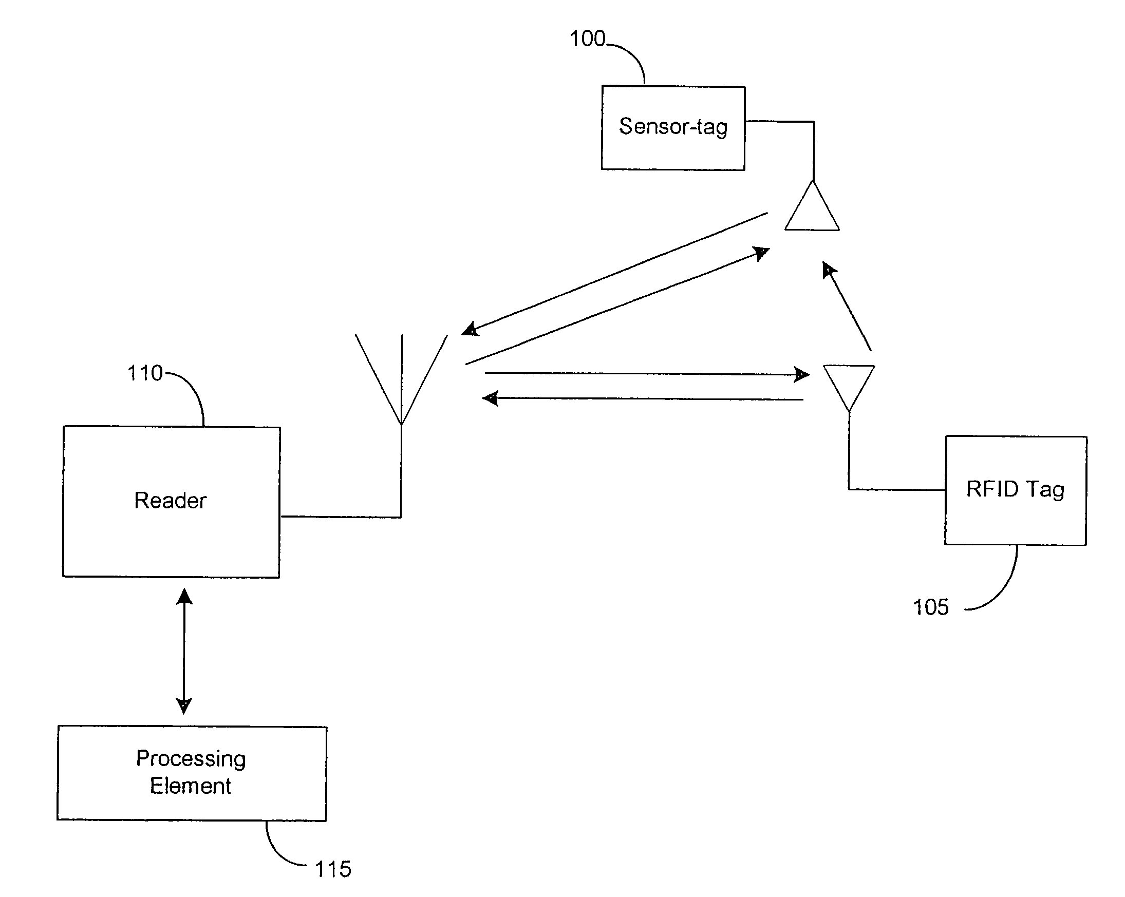
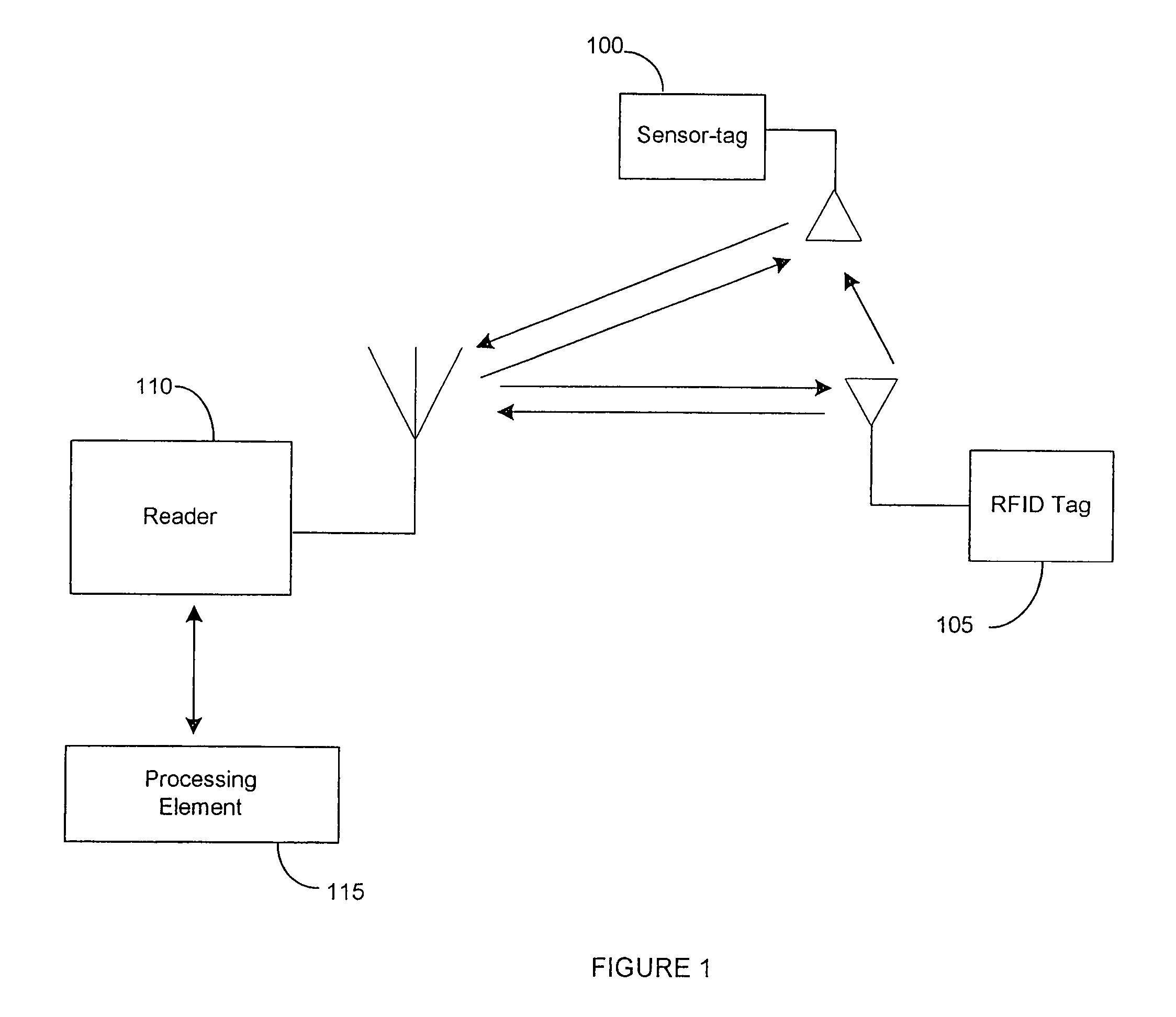
[0029]FIG. 1 illustrates a radio-frequency identification (RFID) system 1 according to the first embodiment of the invention. The RFID system 1 includes at least one sensor-tag 100, at least one object identification RFID tag 105, an RFID reader 110 and a data processing element 115.

[0030]The RFID tag 105 communicates with the reader 110 by backscatter modulation. A certain fraction of power incident on the tag antenna is reflected back to the reader 110. The reflected power is therefore, proportional to the power received by the RFID tag 105.

[0031]The sensor-tag 100 also communicates with the reader 110 using backscatter modulation. The sensor-tag 100 provides additional information to the readers 110 so that RFID tags 105 can be located or tracked easily and accurately. The number of sensor-tags 100 in the RFID system 1 is a design parameter and would depend upon desired accuracy in the localization and tracking. The more sensor-tags 100 the RFID system 1 has, the higher the accur...


PUM


Abstract

A radio frequency identification (RFID) system and method for tracking and locating an RFID tag is disclosed. The system includes a reader, an identification tag, at least one sensor-tag and a data processing element. The reader is used to initiate a query for an object with an RFID tag. The identification tag is attached to the object. The RFID tag responds to the query. At least one sensor-tag is positioned near the RFID tag. The at least one sensor-tag functions to receive the response of the RFID tag. The sensor-tag determines whether the identification tag is within a predetermined sensor-tag range. Based upon this determination, the at least one sensor-tag communicates a response signal to the reader when the at least one sensor-tag receives a predetermined request signal from the reader. Based on the responses of the sensor-tags, the location of the object with the responding RFID tag can be calculated.

Description

CROSS-REFERENCE TO U.S. PROVISIONAL APPLICATION[0001]This Application claims benefit of U.S. Provisional Application No. 60 / 796,705 filed May 1, 2006.FIELD OF THE INVENTION[0002]The invention relates to a location system for radio frequency identification tags. More particularly, the invention relates to a system and method for locating and tracking any motion of an object with an attached RFID tag.BACKGROUND OF THE INVENTION[0003]Radio-Frequency Identification (RFID) relates to identification of objects by using electromagnetic radiation. RFID systems typically include two types of components, (1) RFID readers and (2) RFID tags.[0004]RFID readers are transmitters of radio signals that are connected to external electric power sources. This power drives their antennas and creates radio waves. The RFID tags are integrated circuits that contain radio-frequency circuitry and information that identifies the tags. This invention is related to RFID systems in which tags communicate with th...

Claims


Application Information

Patent Timeline
Patent Type & Authority Patents(United States)
IPC IPC(8): G08B1/08
CPCG08B13/1427G08B21/0275G06K2017/0045
Inventor DJURIC, PETAR M.ATHALVE, AKSHAY
Owner DJURIC PETAR M
Learn More