
Method for producing a three-dimensional digital x-ray image

Inactive Publication Date: 2010-10-12
GE HEALTHCARE FINLAND
View PDF11 Cites 6 Cited by
  • Summary
  • Abstract
  • Description
  • Claims
  • Application Information

AI Technical Summary

Benefits of technology

[0009]The aim of the present invention is to provide a method by means of which the artefacts in a tomographic 3D image can be eliminated and, in addition, the Image quality be improved in areas where conventional 3D imaging based on projection imaging is insufficient, for example, in longitudinal imaging of the jaw bone. To achieve this aim, the method according to the invention is characterised in that in the method, at least one of the images used as input in the method is taken as a tomosynthetic slice image of a region of interest in the object of imaging.

Problems solved by technology

Reasons for this are the minimization of the radiation dosage and the size limitations of the detector.
The problem with local tomography is that objects at a distance from the ROI can be seen in the projections and cause artifacts (errors due to calculation) in the reconstruction.

Method used


Image

  • Method for producing a three-dimensional digital x-ray image
  • Method for producing a three-dimensional digital x-ray image
  • Method for producing a three-dimensional digital x-ray image

Examples


Embodiment Construction

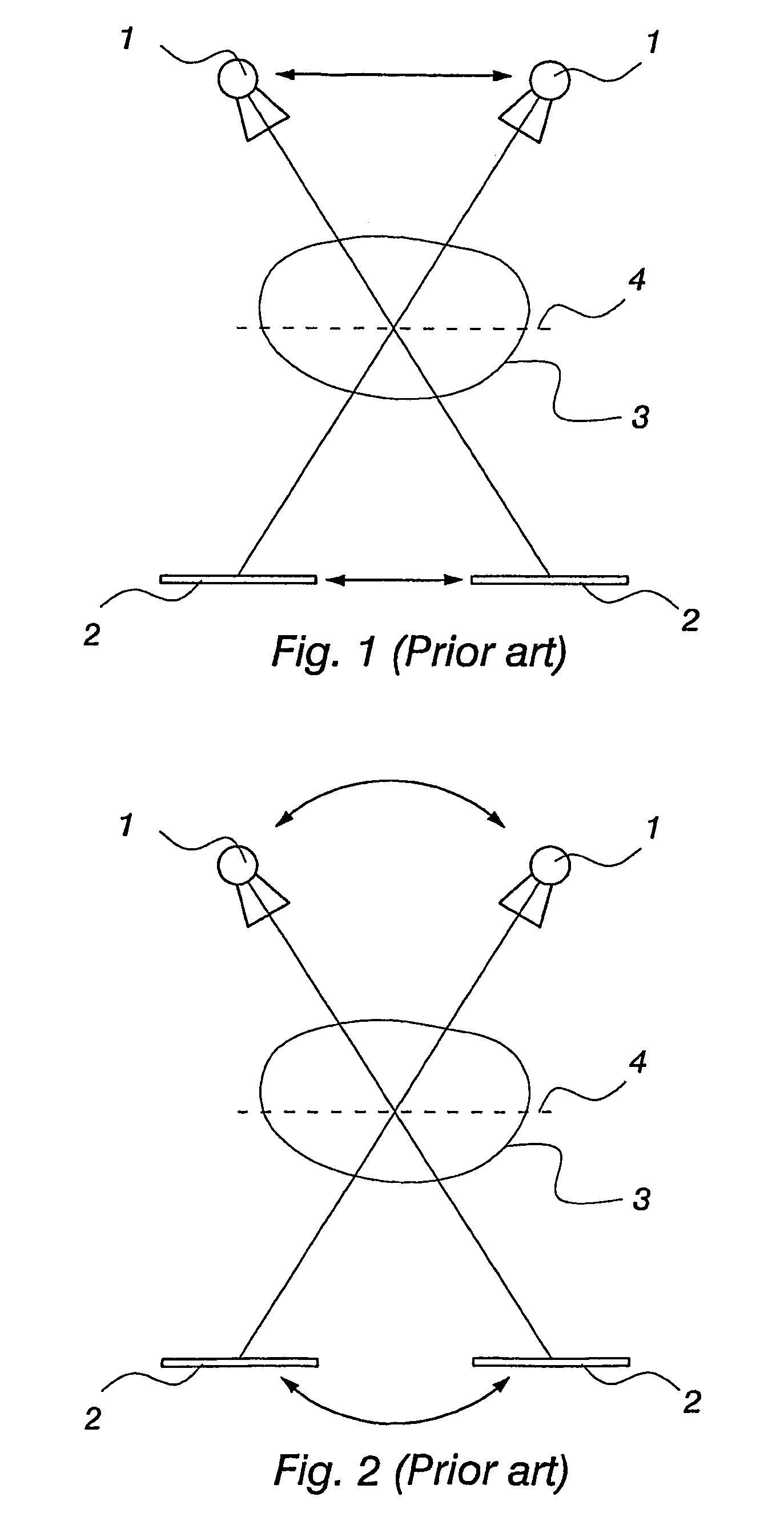
[0015]FIG. 1 shows diagrammatically the principle of conventional tomosynthetic imaging. Reference numeral 1 denotes the x-ray source, reference numeral 2 the detector receiving the radiation that has passed through the object of imaging 3, and reference numeral 4 the in-focus plane. Moving the radiation source 1 and the detector 2 simultaneously, at the same speed, in opposite directions will produce sharp image areas on the in-focus plane 4, whereas distant objects become blurred. FIG. 2 shows another conventional method for implementing tomosynthetic imaging. In this method, the x-ray source 1 and the detector 2 are at a fixed distance from one another, turning as an integrated unit around the in-focus plane 4.

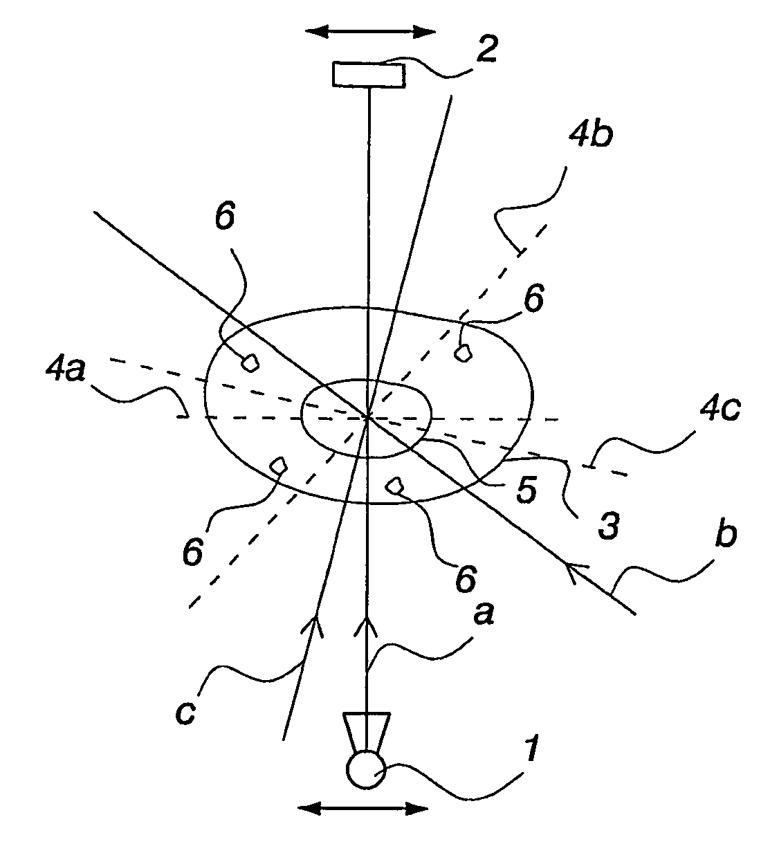
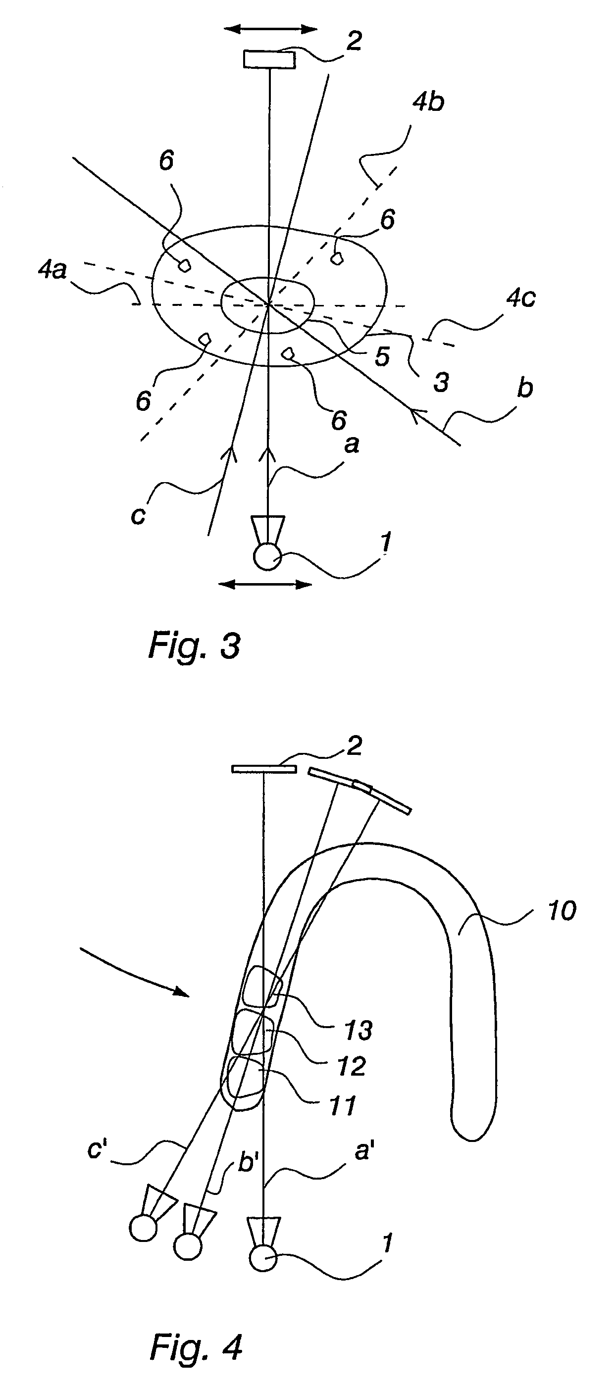
[0016]FIG. 3 shows diagrammatically a method of implementation according to the invention. Of the region of interest 5 inside the object 3 being imaged is first taken—for example from three directions a, b and c—a tomosynthetic slice image along the corresponding in-focus p...


PUM


Abstract

The present invention relates to a method for producing a three-dimensional digital x-ray image by using digital x-ray images taken of the object from at least two different directions as input for a reconstruction algorithm. In the method, at least one of the images used as input is taken as a tomosynthetic slice image of a region of interest (5) in the object (3) of imaging.

Description

CROSS REFERENCE TO RELATED APPLICATION[0001]The present application is the U.S. national stage application of International Application PCT / FI2004 / 000417, filed Jul. 1, 2004, which international application was published on Jan. 12, 2006, as International Publication WO 2006 / 003235.BACKGROUND OF THE INVENTION[0002]The invention relates to a method for producing a three-dimensional (3D) digital x-ray image by using digital x-ray images taken of the object from at least two different directions as input for a reconstruction algorithm. A reconstruction algorithm refers to an algorithm by means of which two-dimensional or three-dimensional x-ray image information on the object being imaged is reconstructed, that is, produced.[0003]Conventionally, the input used for a reconstruction algorithm in 3D x-ray imaging consists of a selection of projections taken from different directions, giving as a result a three-dimensional voxel representation of the tissue being imaged. For example, U.S. ...

Claims


Application Information

Patent Timeline
IPC IPC(8): A61B6/00
CPCA61B6/025A61B6/14G06T11/005G06T2211/436A61B6/51
Inventor SILTANEN, SAMULIJOUHIKAINEN, PETRI
Owner GE HEALTHCARE FINLAND
Learn More