Computer modeling of physical scenes

a computer and physical scene technology, applied in the computer field, can solve the problems of not being able to achieve a satisfying degree of realism, and still being too processing intensive to be performed in real tim

Active Publication Date: 2010-10-12
SAAB AB
View PDF2 Cites 44 Cited by
  • Summary
  • Abstract
  • Description
  • Claims
  • Application Information

AI Technical Summary

Benefits of technology

[0006]The object of the present invention is therefore to provide an improved three-dimensional modeling a physical scene, which alleviates the above problems and thus offers a means for generating the depth map in real time.

Problems solved by technology

Although Pollefeys' algorithm is robust and reliable it is still too processing intensive to be performed in real time.
However, these strategies provide a substantially lower resolution (which is dependant on the projected light), and therefore cannot be used to accomplish a satisfying degree of realism.

Method used


Image

  • Computer modeling of physical scenes
  • Computer modeling of physical scenes
  • Computer modeling of physical scenes

Examples


Embodiment Construction

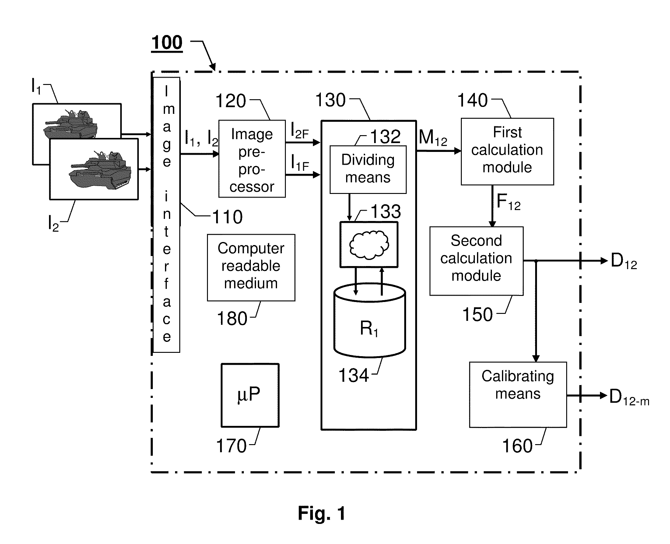
[0027]An apparatus 100 for automatically modeling a physical scene according to one embodiment of the invention is illustrated by means of a block diagram in FIG. 1. It is presumed that the scene to be modeled includes at least one object, such as a building, a vehicle or a tree, which has certain dimensions and surface properties.

[0028]The apparatus 100 includes an image interface 110, an image preprocessor 120, a matching module 130 and at least one calculation module 140 and 150. Preferably, the apparatus 100 also contains a central processing unit 170 for controlling the operation of the other units and modules therein. The central processing unit 170, in turn, operates according to a computer program, which is stored in a computer readable medium 180 associated with the apparatus 100.

[0029]The image interface 110 is adapted to receive a number of images I1 and I2 (at least two) of the scene to be modeled. Preferably, the image interface 110 is adapted to be connected to a camer...


PUM


Abstract

The present invention relates to automatic modeling of a physical scene. At least two images (I1, I2) of the scene are received, which are taken from different angles and / or positions. A matching module (130) matches image objects in the first image (I1) against image objects in the second image (I2), by first loading pixel values for at least one first portion of the first image (I1) into an artificial neural network (133). Then, the artificial neural network (133) scans the second image (I2) in search of pixels representing a respective second portion corresponding to each of the at least one first portion; determines a position of the respective second portion upon fulfillment of a match criterion; and produces a representative matching result (M12). Based on the matching result (M12), a first calculation module (140) calculates a fundamental matrix (F12), which defines a relationship between the first and second images (I1, I2). Based on the fundamental matrix (F12), in turn, a second calculation module (150) calculates a depth map (D12), which describes distance differences between a set of image points in the first image (I1) and a corresponding set of image points in the second image (I2). Finally, the depth map (D12) constitutes a basis for a synthetic model of the scene.

Description

Cross Reference to Related Applications[0001]This application is a national stage application of International Application PCT / EP2005 / 052640, filed 8 Jun. 2005, designating the United States of America.THE BACKGROUND OF THE INVENTION AND PRIOR ART[0002]The present invention relates generally to image based modeling. More particularly the invention relates to a method of automatically modeling a physical scene and a corresponding apparatus. The invention also relates to a computer program and a computer readable medium.[0003]Modern image processing has provided us with highly efficient tools for registering the properties of complex physical scenes. The advances in computer graphics have also enabled a real time visualization of such scenes.[0004]Pollefeys, M., “Tutorial on 3D Modeling from Images”, Katholike Universiteit, Leuven, 26 Jun. 2000, Dublin, Ireland, in conjunction with ECCV 2000 describes how a three-dimensional surface model of a scene can be obtained from a sequence of ...

Claims


Application Information

Patent Timeline
Patent Type & Authority Patents(United States)
IPC IPC(8): G06T17/00G06T7/00
CPCG06T7/0024G06T7/0075G06T7/30G06T7/593
Inventor MODEN, ANDERS
Owner SAAB AB
Why Eureka
Try Eureka