Method to increase the safety integrity level of a control system

a control system and safety integrity technology, applied in the direction of program control, electric controllers, instruments, etc., can solve the problems of complex electronics, difficulty in verifying correctness, etc., and achieve the effect of increasing the safety level, reducing the complexity of implementation and maintenance, and increasing the flexibility of the use of single-unit controllers

a control system and safety integrity technology, applied in the direction of program control, electric controllers, instruments, etc., can solve the problems of complex electronics, difficulty in verifying correctness, etc., and achieve the effect of increasing the safety level, reducing the complexity of implementation and maintenance, and increasing the flexibility of the use of single-unit controllers

US7813820B2Active Publication Date: 2010-10-12ABB (SCHWEIZ) AG

Image

  • Method to increase the safety integrity level of a control system
  • Method to increase the safety integrity level of a control system
  • Method to increase the safety integrity level of a control system

Examples


Embodiment Construction

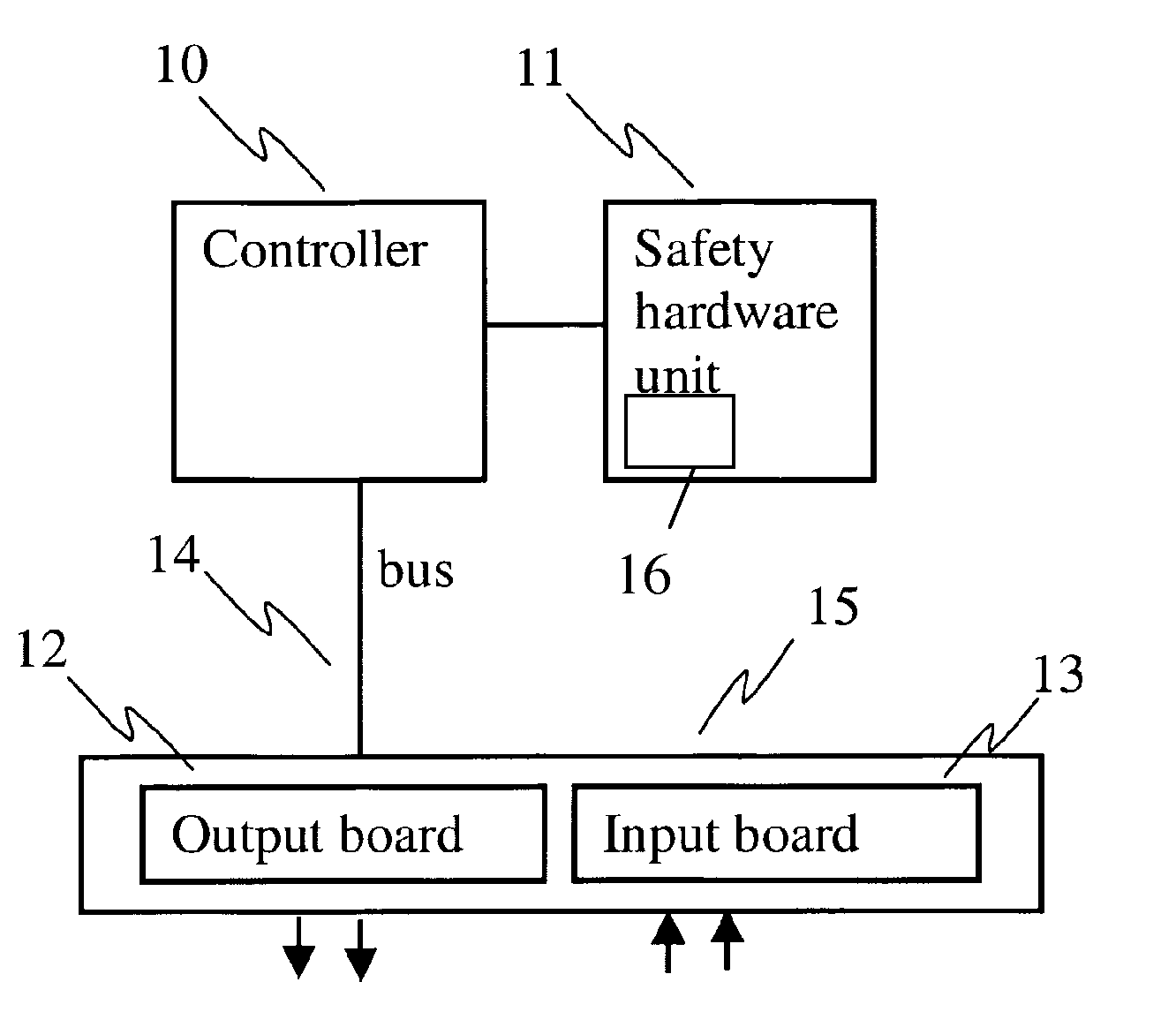
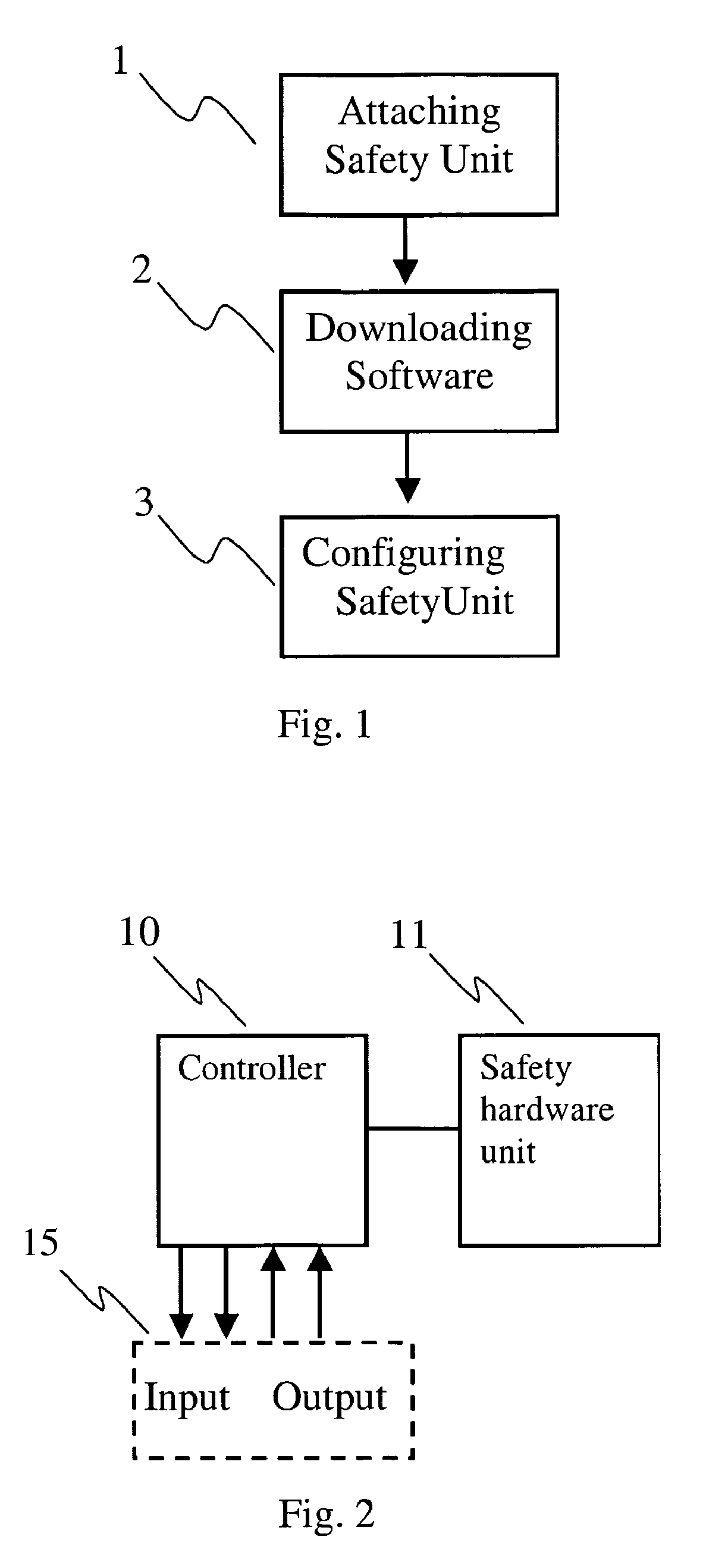
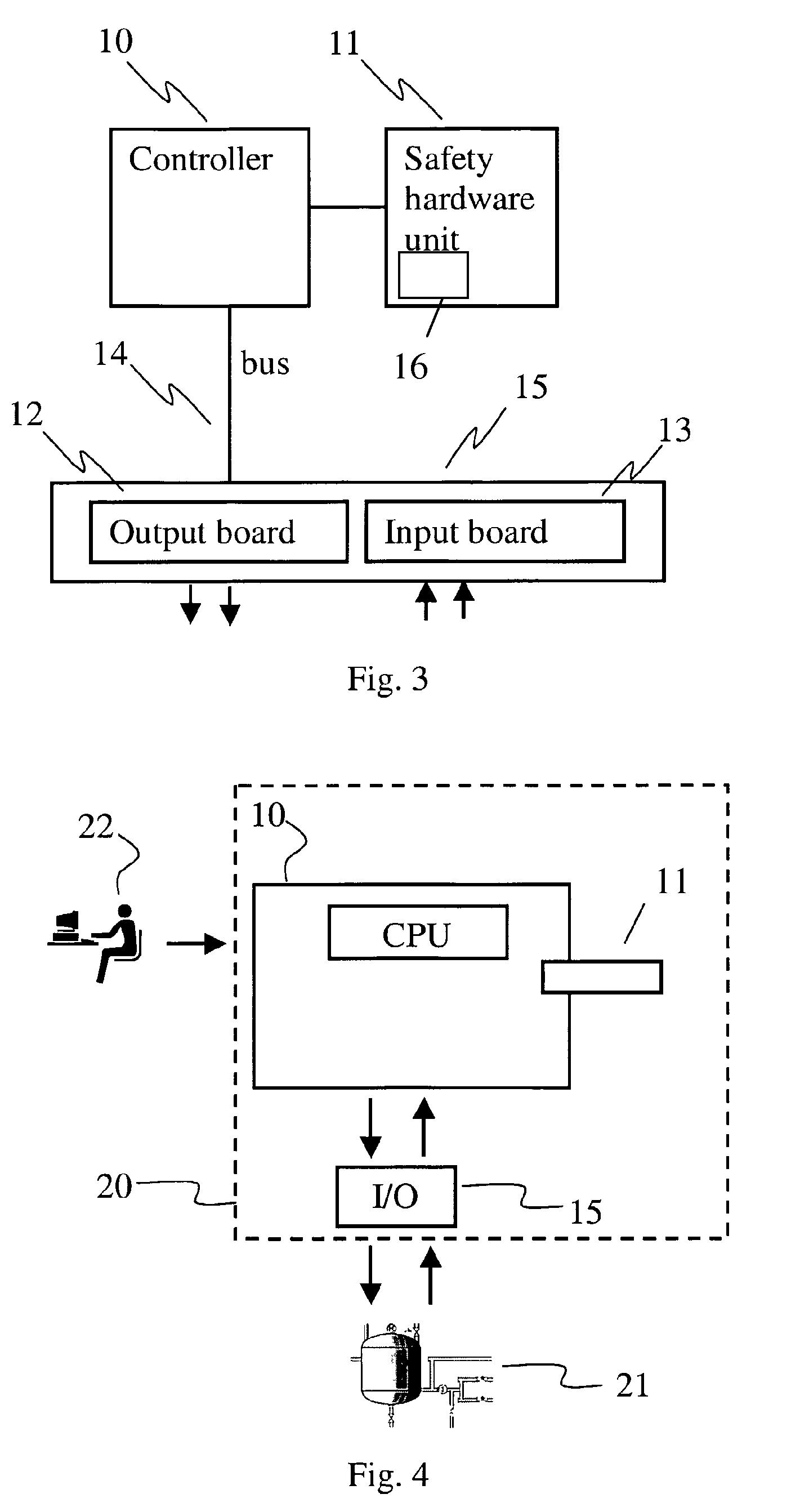
[0019]FIG. 1 shows an overview of a method according to the invention. The method provides an increased safety-integrity level of a Controller 10 such as an Industrial Controller of an Industrial Control System. Examples of a Controller is a Programmable Logic Controller (PLC) and a field controller.

[0020]In this description a Controller has the purpose of collecting measurements and controlling real-world objects connected to a Control System. Examples of real world objects are valves, motors, pumps, compressors, switchgear, conveyor belts, a product, a raw material, or a batch.

[0021]By safety-integrity level is meant a controller which meets de-facto standard safety-integrity levels or standard safety-integrity levels, such as SIL 1, SIL 2, SIL 3 or SIL 4 (SIL according to the standard IEC 61508 or later IEC standards).

[0022]FIG. 1 shows that the method comprises a step of attaching 1 a safety-hardware unit 11 (shown in FIG. 2) to the Controller 10. The safety-hardware unit 11 com...


PUM


Abstract

Controller capable of executing non-safety-related control logic. A safety module is added to the controller in order to increase the safety-integrity level of a control system. The controller is able to execute safety-related control of real-world objects. Such a control system may exist at an offshore production platform or in a hazardous area of a chemical plant.

Description

TECHNICAL FIELD[0001]The present invention relates to supervision, diagnostic and diversity of execution of control algorithms in the context of control systems. A device comprises functionality, which adds security features to a controller and enables the controller to meet requirements for a safety-control system. Such a system needs diagnostic in order to ensure that no accidents take place which otherwise could harm people, equipment or the environment.BACKGROUND ART[0002]Industrial control systems are for instance applied in manufacturing and process industries, such as chemical plants, oil production plants, refineries, pulp and paper mills, steel mills and automated factories. Industrial control systems are also widely used within the power industry. Such industrial control systems may need to comprise or be combined with devices which add safety features. Example of processes which require additional safety features other than what a standard industrial control system provid...

Claims


Application Information

Patent Timeline
12 Oct 2010
Publication
US7813820B2
IPC
G05B9/02; G05B11/01; G05B19/042
CPC
G05B9/02; G05B19/0428; G05B2219/24008; G05B2219/25323
Inventors
OPEM, AUDUN; GUNNMARKER, MATS