
Hybrid method for enforcing curvature related boundary conditions in solving one-phase fluid flow over a deformable domain

a boundary condition and hybrid method technology, applied in the field of systems and methods for simulating a single-phase fluid flow, can solve problems such as numerical instability simulations, affecting the simulation accuracy, and creating curvature variations

Inactive Publication Date: 2010-10-12
SEIKO EPSON CORP
View PDF22 Cites 12 Cited by
  • Summary
  • Abstract
  • Description
  • Claims
  • Application Information

AI Technical Summary

Benefits of technology

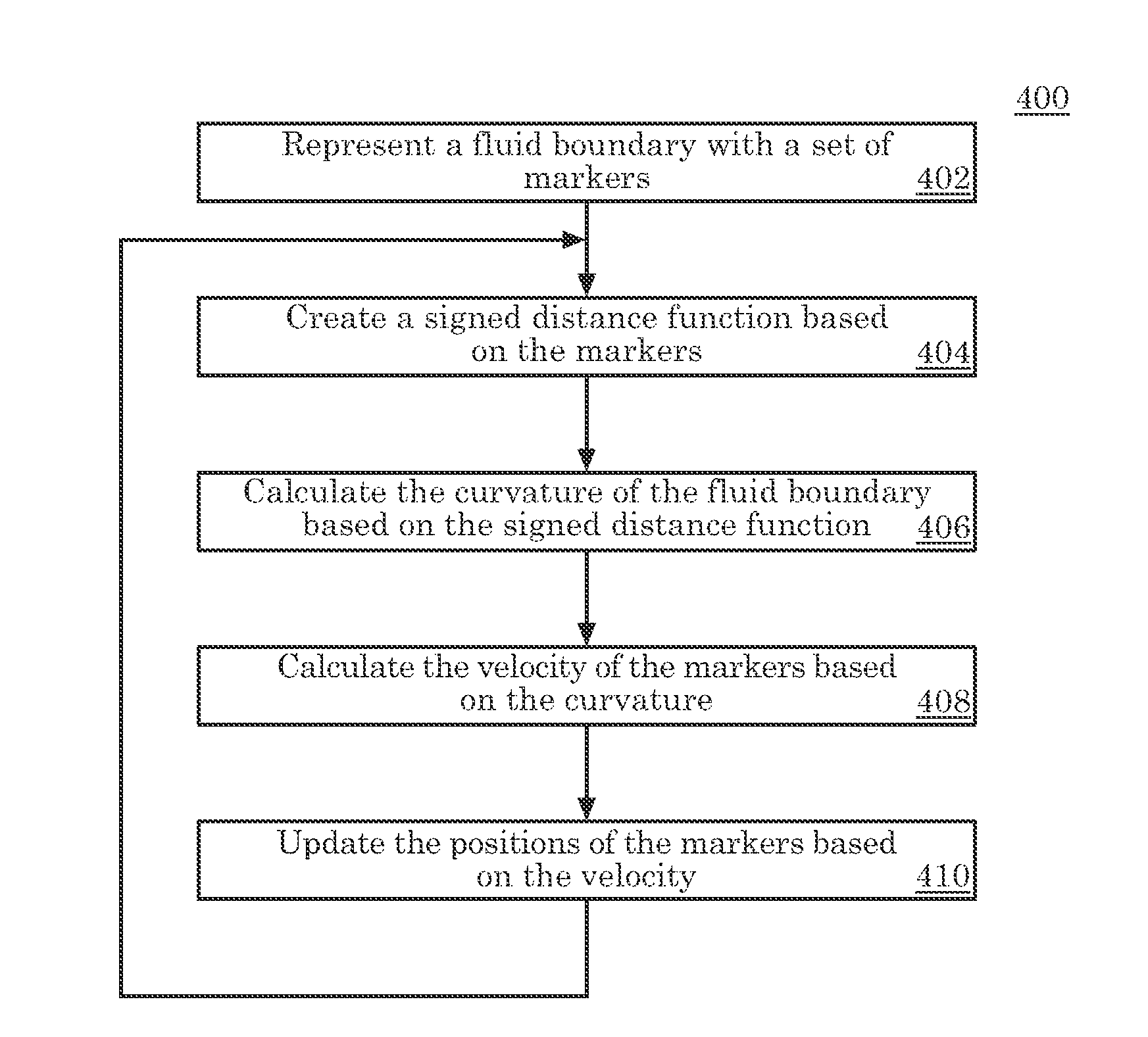
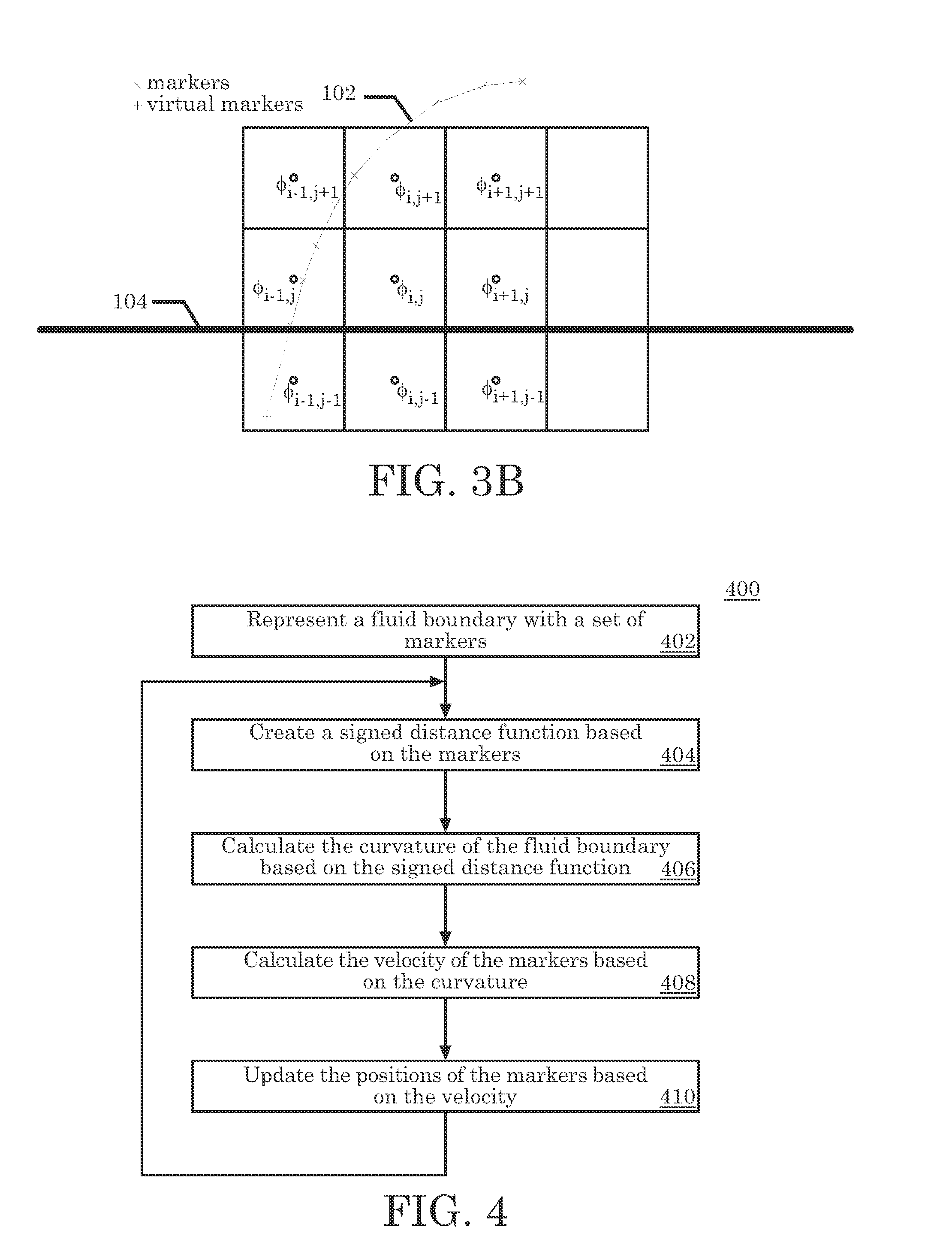
The present invention is a system or method for simulating the flow of single-phase fluid flow. It uses markers to represent the boundary of the fluid at different points in time. The system evaluates the curvature of the boundary based on the markers in the non-fluid space and calculates the velocity of the fluid based on this curvature. The position of the fluid boundary is then updated based on the velocity of the fluid. This invention allows for more accurate and precise simulation of fluid flow.

Problems solved by technology

Small errors in the positions of the marker can cause errors in the second derivatives, which can create variations in the curvature.
This can lead to numerically unstable simulations, which exhibit unrealistic oscillations.
Front tracking methods have not been developed for single-phase fluid flow because there is no fluid on the other side of the boundary thus creating a jump condition in the system variable and their derivatives.
Problems arise when handling the boundary between the two fluids.
This jump condition results in a discontinuity in system variables and their derivatives at the boundary.
Smoothing these variables brings its own problems.
Another problem with prior art methods is inability to conserve mass.

Method used


Image

  • Hybrid method for enforcing curvature related boundary conditions in solving one-phase fluid flow over a deformable domain
  • Hybrid method for enforcing curvature related boundary conditions in solving one-phase fluid flow over a deformable domain
  • Hybrid method for enforcing curvature related boundary conditions in solving one-phase fluid flow over a deformable domain

Examples


numerical example

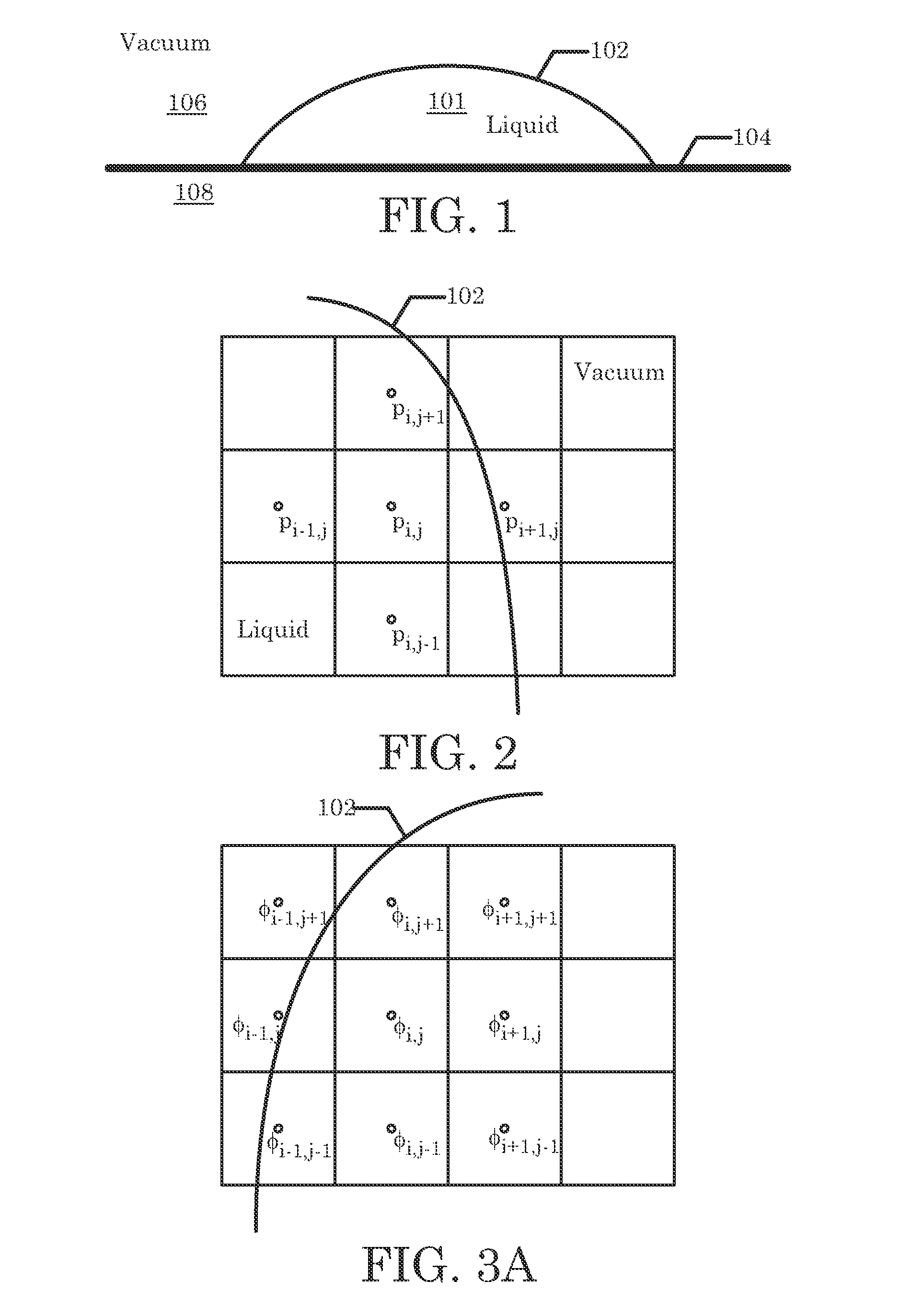
[0057]A numerical example of the present invention is used to illustrate the advantages of using our hybrid method of enforcing the boundary condition. Assume a liquid drop is attached at two endpoints to a substrate 108. The liquid is an incompressible fluid 101. Initially it assumes a circular shape. There is a small entrance flow at the bottom of the drop, which is described as a time independent parabolic profile flow. Since the Reynolds number is low, we are solving a creeping flow equation with the incompressibility condition enforced. The Stokes equation (15) and the incompressibility condition (16) may be considered the governing equations for this problem.

[0058]ρ⁢∂u∂t=-∇p+μ⁢∇2⁢u(15)

∇·u=0  (16)

[0059]The liquid drop is in a vacuum 106. We assume that the pressure in vacuum 106 is zero. Hence, the boundary condition along the liquid-vacuum surface 102 is equation (3) discussed above. A projection method is utilized to solve the above equations. In this example, the surface ten...


PUM


Abstract

An embodiment of the present invention may be a system or method for simulating the flow of a single-phase fluid flow. Markers represent a moving fluid boundary of the single-phase fluid at a first point in time. The moving fluid boundary separates a simulation space into a fluid space and a non-fluid space. The single-phase fluid inhabits the fluid space. A signed distance function is evaluated at points surrounding the moving fluid boundary based upon markers. The curvature of the moving fluid boundary based on the signed distance function is evaluated near the markers in the non-fluid space. The curvature is not evaluated at the moving fluid boundary. The velocity of the fluid is calculated based upon the curvature of the level set in the non-fluid space. Update the position of the moving fluid boundary at a second point in time based on the velocity of the fluid.

Description

BACKGROUND OF THE INVENTION[0001]1. Field of the Invention[0002]The present invention relates to systems and methods for simulating a single-phase fluid flow enclosed by a deformable boundary while enforcing curvature related boundary conditions.[0003]2. Description of the Related Art[0004]The present invention is directed towards the study of single-phase fluids. A single-phase fluid, as used in the present invention refers to a pure fluid or a mixture. A boundary encapsulates this single-phase fluid, over time the boundary may evolve and move through space. The solution domain is limited to an area delimited by the boundary. For the purposes of the present invention, the effect of an interface, if any that does form between elements of such a mixture may be ignored when considering the motion of the boundary.[0005]Motion of the boundary may be governed by one or more governing equations. The boundary may be defined by a set of markers. For some systems the governing equations may ...

Claims


Application Information

Patent Timeline
Patent Type & Authority Patents(United States)
IPC IPC(8): G06G7/50
CPCG06F17/5018G06F2217/16G06F2111/10G06F30/23
Inventor ZHANG, JIEYU, JIUN-DER
Owner SEIKO EPSON CORP
Learn More