Travel support mechanism for movable conveyor bridge

a conveyor bridge and travel support technology, applied in the direction of travelling bridges, loading/unloading, process efficiency improvement, etc., can solve the problems of limited horizontality of conveyor bridges, difficult to keep conveyor bridges horizontal at other steering positions, and difficult to move conveyor bridges

Active Publication Date: 2010-10-19
KRUPP FOERDERTECHNIK GMBH +1
View PDF8 Cites 9 Cited by
  • Summary
  • Abstract
  • Description
  • Claims
  • Application Information

AI Technical Summary

Benefits of technology

[0005]The object of the present invention is therefore to provide a travel support device that maintains the position of the conveyor bridge when the conveyor bridge is built of polynominal construction type and is moved along uneven ground or is located on a sloped section of ground.
[0020]The first roller table and the second roller table may have a stopping element. The stopping element prevents movement of the roller means.
[0027]Each chassis has an independent drive. The travel support device is advantageously designed such that control and steering motions do not lead to constraining forces in the conveyor bridge by allowing the bridge to move freely in the longitudinal and transverse directions.

Problems solved by technology

A problem exists in moving a conveyor bridge over uneven ground without introducing the forces that result from the unevenness of the ground to the conveyor bridge.
This is especially a problem in oil sand or tar sand mines and in many different applications.
This is particularly difficult on side slopes or uphill sections since the conveyor bridge must always be directed horizontally (in the lateral direction) to make it possible to convey material.
This arrangement disadvantageously leads to the drawback that the conveyor bridge can only be kept horizontal when the chassis is at right angles (90°) to the conveyor bridge.
As such, keeping the conveyor bridge horizontal at other steering positions is very limited.
This makes it difficult to maneuver the conveyor bridge along uneven or sloped ground.
Further, such a conventional technique can only be used where even and well prepared ground conditions are present, such as in leach pad systems.
As such, the conventional techniques used for leach pad systems are not suited for applications where movable conveyor bridges have to travel about uneven ground conditions, such as sand oil or tar sand mines in which the ground is uneven and sloped since a cylinder arrangement having a greater path of adjustment is necessary to maintain the conveyor bridge in a stable position.
However, the connection to the traveling means with this type of joint does not fully address the problem regarding supporting a polynominal conveyor bridge that is supported by several self-propelled chassis and moving across ground that is uneven and sloped.

Method used


Image

  • Travel support mechanism for movable conveyor bridge
  • Travel support mechanism for movable conveyor bridge
  • Travel support mechanism for movable conveyor bridge

Examples


Embodiment Construction

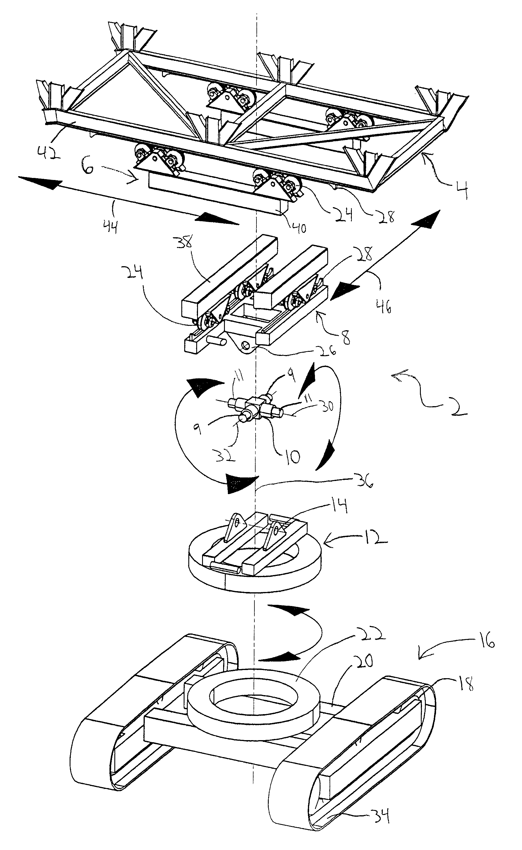
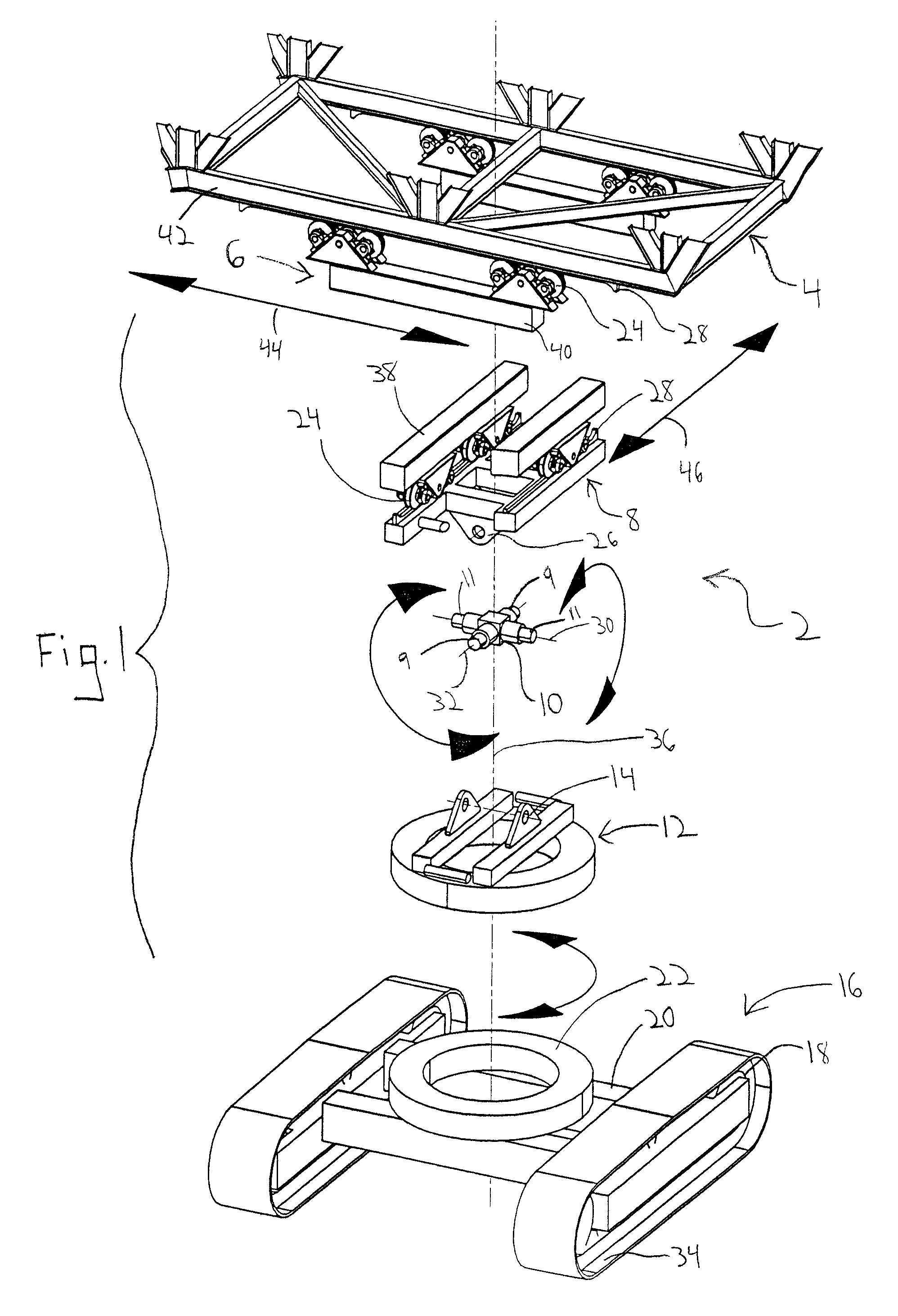
[0044]Referring to the drawings in particular, FIG. 1 shows an exploded perspective view of the travel support device 2 for supporting a conveyor bridge 4. The conveyor bridge 4 is connected to a roller table 6. Roller table 6 is connected to another roller table 8. The roller table 8 has a connection element 26. A two-axis tilting joint 10 is provided. A portion 9 of the joint 10 is connected to the roller table 8 via connection element 26. The joint 10 rotates about a defined longitudinal axis 30. The joint 10 also rotates about a defined axis 32 that transverses the longitudinal axis 30. A swivel joint 12 has a connection mount 14. Another portion 11 of the joint 10 is connected to the swivel joint 12 via connection mount 14. A caterpillar-type (endless track) moving device 16 is provided. The moving device 16 has a chassis 20 and a travel drive 18. The travel drive 18 is connected to an endless track 34 for moving the chassis 20. The chassis 20 is connected to a mount 22. The sw...


PUM


Abstract

A travel support device for a conveyor bridge 4 having a swivel joint 12, a two-axis tilting joint 10 and a roller table 8. A portion of the tilting joint 10 is mounted to the swivel joint 12 and another portion of the tilting joint 10 is mounted to the roller table 8 such that the tilting joint 10 rotates about a defined longitudinal axis 30 and an axis 32 transverse of the longitudinal axis 30.

Description

FIELD OF THE INVENTION[0001]The present invention generally relates to movable conveyors and more particularly pertains to a travel support device for a movable conveyor bridge.BACKGROUND OF THE INVENTION[0002]Movable conveyor bridges are used for conveying material, for example from the site of a mining operation. A problem exists in moving a conveyor bridge over uneven ground without introducing the forces that result from the unevenness of the ground to the conveyor bridge. This is especially a problem in oil sand or tar sand mines and in many different applications. This is particularly difficult on side slopes or uphill sections since the conveyor bridge must always be directed horizontally (in the lateral direction) to make it possible to convey material.[0003]A conventional technique to control the level of the conveyor bridge is to provide a tilting joint in the longitudinal direction having a tilt axis at a right angle to the conveyor bridge. The tilting joint is provided a...

Claims


Application Information

Patent Timeline
Patent Type & Authority Patents(United States)
IPC IPC(8): E01D15/10
CPCB65G65/28B65G41/008Y02P10/20
Inventor BREWKA, CHRISTOF
Owner KRUPP FOERDERTECHNIK GMBH
Why Eureka
Try Eureka