Liquid aspirator

a liquid aspirator and liquid technology, applied in the direction of liquid handling, machines/engines, cleaning equipment, etc., can solve the problem of comparatively time-consuming aspiration of liquid or sludge, and achieve the effect of minimal maintenance and minimal sensitivity

Active Publication Date: 2010-10-19
OASE GMBH
View PDF11 Cites 9 Cited by
  • Summary
  • Abstract
  • Description
  • Claims
  • Application Information

AI Technical Summary

Benefits of technology

[0004]According to the invention, this problem is solved by a liquid aspirator wherein the receptacle has at least two separate receiving chambers and a control, by which alternatingly filling of one of the receiving chambers with liquid is realized while at the same time the other receiving chamber is drained. By providing the receptacle of the liquid aspirator with at least two separate receiving chambers and by providing a control with which an alternating filling with liquid and draining of the receiving chambers can be initiated, the liquid or sludge aspiration process can be continuously performed because liquid can always be sucked into one of the chambers while the other chamber is simultaneously drained and room is thus provided for the next filling.
[0006]In an especially preferred embodiment, only one aspirator motor is provided and the control is designed such that the vacuum side of the motor is connected alternatingly to the different receiving chambers so that in this case the receiving chambers can also be alternatingly filled and drained. The aspirator motor can therefore run continuously and is therefore more efficient. In the receiving chamber to which the vacuum side of the aspirator motor is currently connected, liquid is sucked in while no vacuum is applied to the other receiving chamber so that the liquid contained therein can drain under its own weight. As soon as this chamber is completely or mostly drained, the process is reversed and the presently empty chamber is connected to the vacuum side of the aspirator motor in order to be filled again.
[0008]The control can be realized electronically but also by time control. However, it is preferably embodied as a mechanical control or switch because, in this way, minimal maintenance is required and minimal sensitivity relative to external effects and possible faulty usage, for example, tilting of the aspirator, is achieved.

Problems solved by technology

However, after each filling process of the receptacle an aspiration break is required in which the receptacle must be emptied.
The liquid or sludge aspiration is therefore comparatively time-consuming.

Method used


Image

  • Liquid aspirator
  • Liquid aspirator
  • Liquid aspirator

Examples


Embodiment Construction

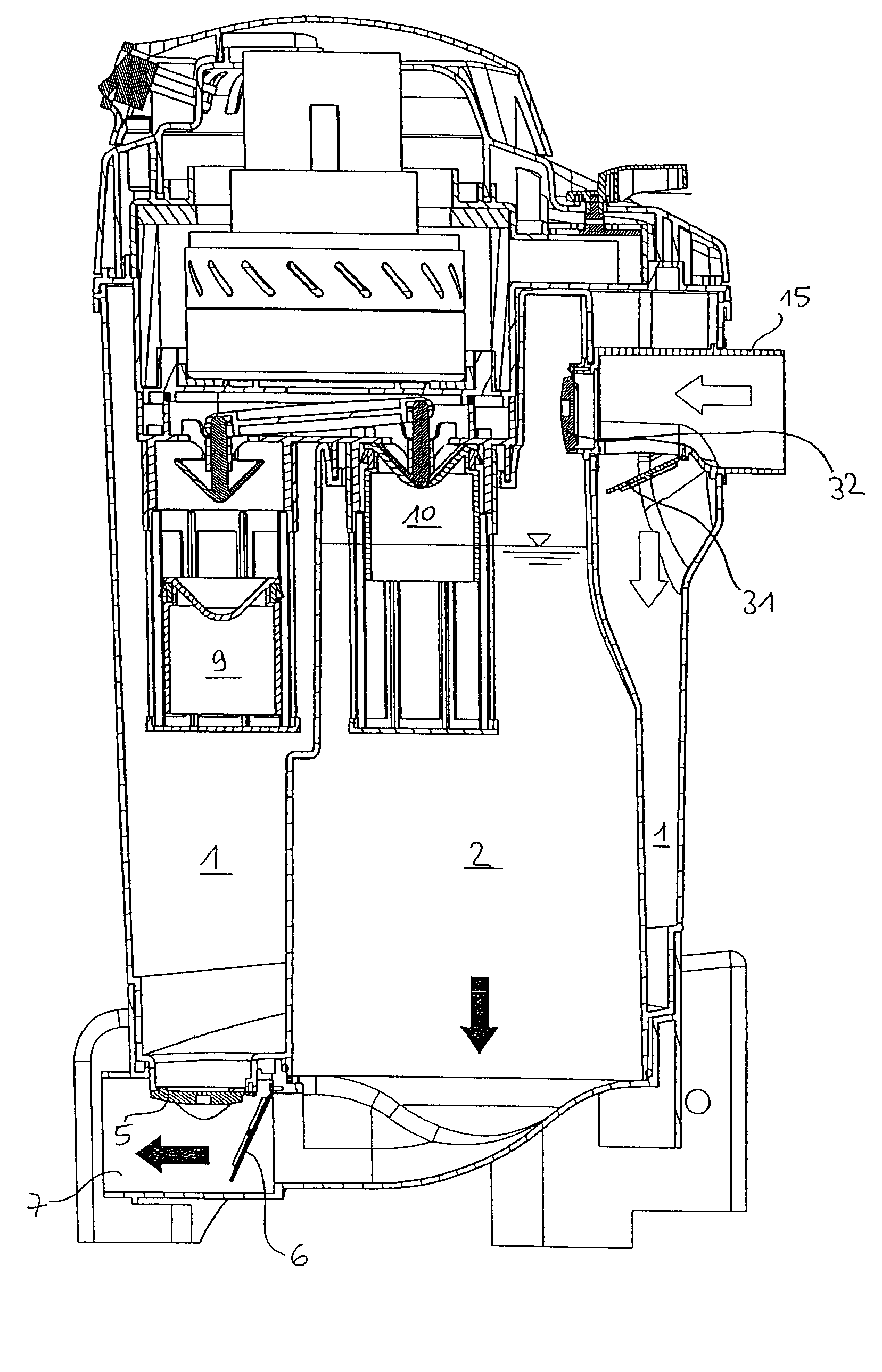
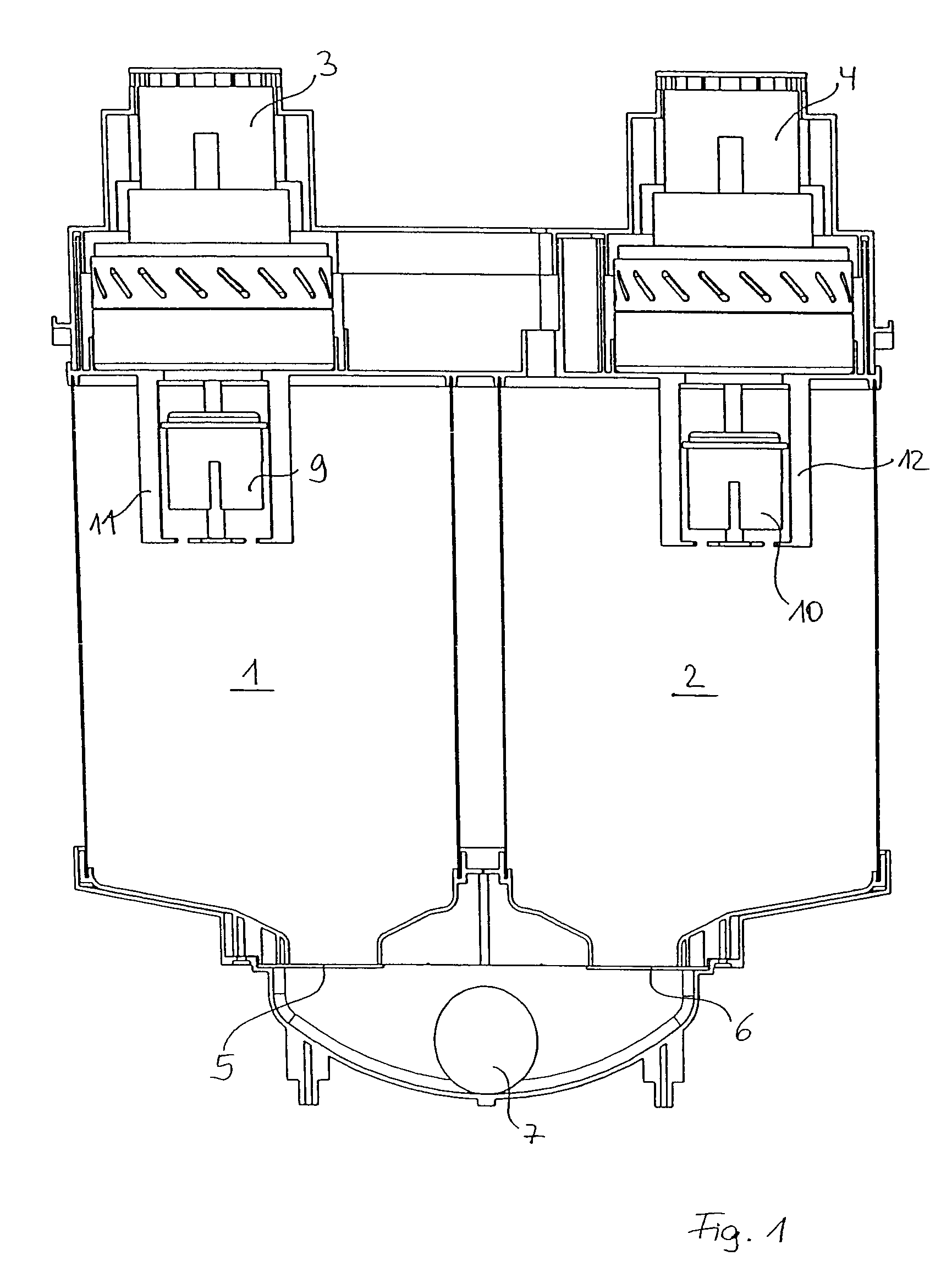
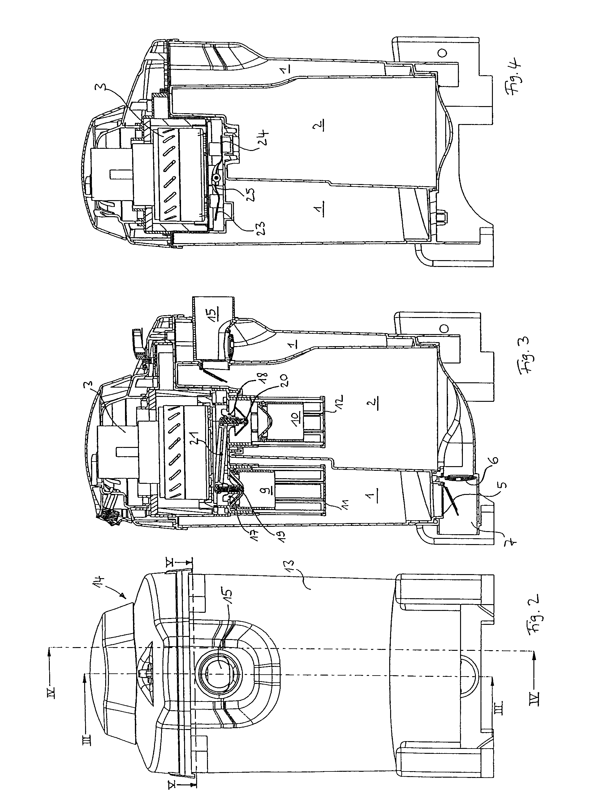
[0021]In FIG. 1 a liquid aspirator is schematically shown that is provided with two separate receiving chambers 1, 2. Each receiving chamber 1, 2 has associated therewith its own aspirator motor 3, 4. By means of the aspirator motors 3, 4, a vacuum can be generated in the chambers 1, 2 so that by means of a vacuum connector, not illustrated, that opens in the upper area into the receiving chambers 1, 2, liquid can be sucked into the receiving chambers 1, 2. If, for example, the receiving chamber 1 is filled to a predetermined level with liquid, the aspirator motor 3 will shut off. Under the liquid's own weight, the vacuum flap 5 that closes off the receiving chamber 1 at the bottom will open and the liquid will drain through the drainage 7 and a drain element connected thereto, for example, a drain hose. By means of a control it is ensured that filling with liquid and draining of the receiving chambers 1, 2 will take place alternatingly so that continuously liquid is sucked in and d...


PUM


Abstract

A liquid aspirator, in particular for liquids containing solids such as sludge, has a receptacle into which liquid can be sucked in by an aspirator motor through a vacuum connector and from which the liquid can drain through a drainage. The receptacle has at least two separate receiving chambers and a control that controls that the receiving chambers are filled alternatingly with liquid while the receiving chambers that are not being filled are drained. The receiving chambers are sealable relative to the vacuum side of the aspirator motor by main valves that are preferably mechanically connected.

Description

BACKGROUND OF THE INVENTION[0001]The invention relates to a liquid aspirator for vacuuming or transporting liquids, in particular liquids containing solids such as sludge or the like. Such a liquid aspirator is disclosed in DE 102 40 804 A1. It has a receptacle in which by means of an air aspiration motor a vacuum is generated. As a result of the vacuum, the liquid or the sludge is sucked into the receptacle through a vacuum connection and, after filling the receptacle and switching off the motor, can be drained from the receptacle through a drainage and a drain element, usually in the form of a hose, and can be guided to a desired location.[0002]Such sludge aspirators operate reliably because damage to the motor by entrained solids is prevented as a result of separation of motor and liquid or sludge to be transported by means of the receptacle. However, after each filling process of the receptacle an aspiration break is required in which the receptacle must be emptied. The liquid o...

Claims


Application Information

Patent Timeline
Patent Type & Authority Patents(United States)
IPC IPC(8): B67C3/16A47L7/00A47L9/22E03F5/22E03F7/10F04F3/00
CPCA47L7/0028A47L7/0038A47L7/0042E03F5/22F04F3/00A47L9/22Y10T137/469Y10T137/3109
Inventor HOFFMEIER, DIETERWESSELMEIER, REINHARDWAGNER, UTZ
Owner OASE GMBH
Why Eureka
Try Eureka