Structural member joints

a technology of structural members and joints, applied in the direction of rod connections, couplings, building repairs, etc., can solve the problems of insufficient holding power of screw threads in wood or other soft materials, and insufficient strength of joints

Inactive Publication Date: 2010-10-19
KAUPPILA RICHARD W
View PDF23 Cites 15 Cited by
  • Summary
  • Abstract
  • Description
  • Claims
  • Application Information

AI Technical Summary

Problems solved by technology

For large member joints, screw threads in wood or other soft material have insufficient holding power.
All of these prior methods have disadvantages, primarily in the cost or time involved in making the joint due to the need to machine the wood or to install costly, complicated connectors or result in a joint of inadequate strength.
Many such joints use components which are conspicuously exposed, to be unsightly.

Method used


Image

  • Structural member joints
  • Structural member joints
  • Structural member joints

Examples


Embodiment Construction

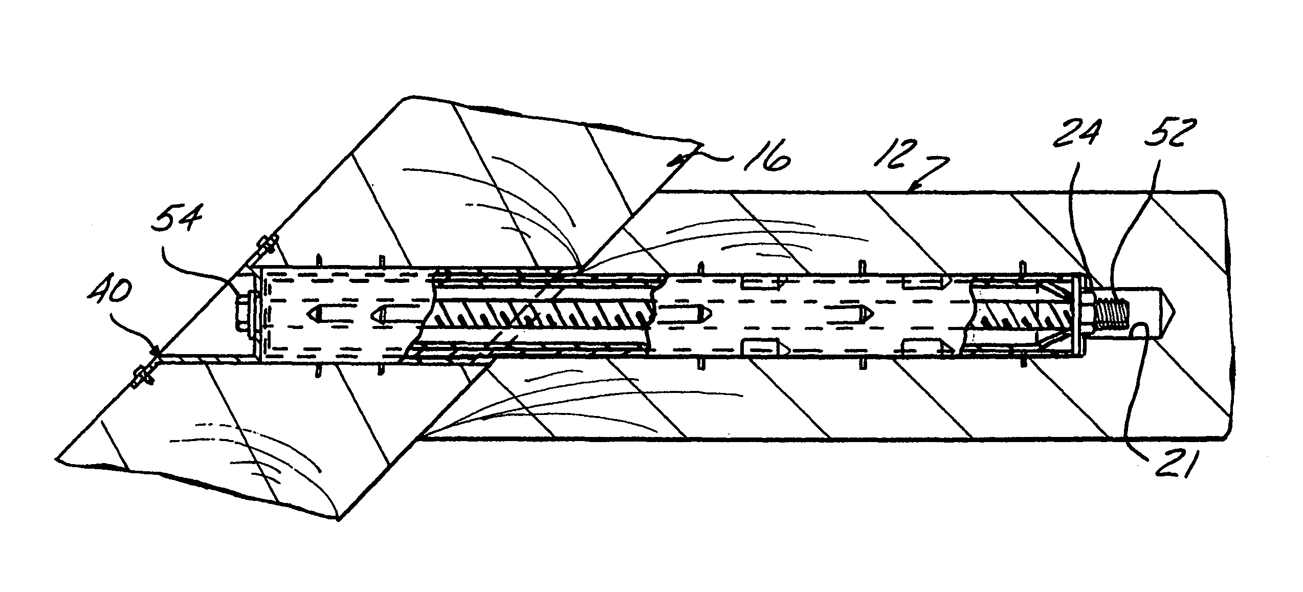
[0038]In the following detailed description, certain specific terminology will be employed for the sake of clarity and a particular embodiment described in accordance with the requirements of 35 USC §112, but it is to be understood that the same is not intended to be limiting and should not be so construed inasmuch as the invention is capable of taking many forms and variations within the scope of the appended claims.

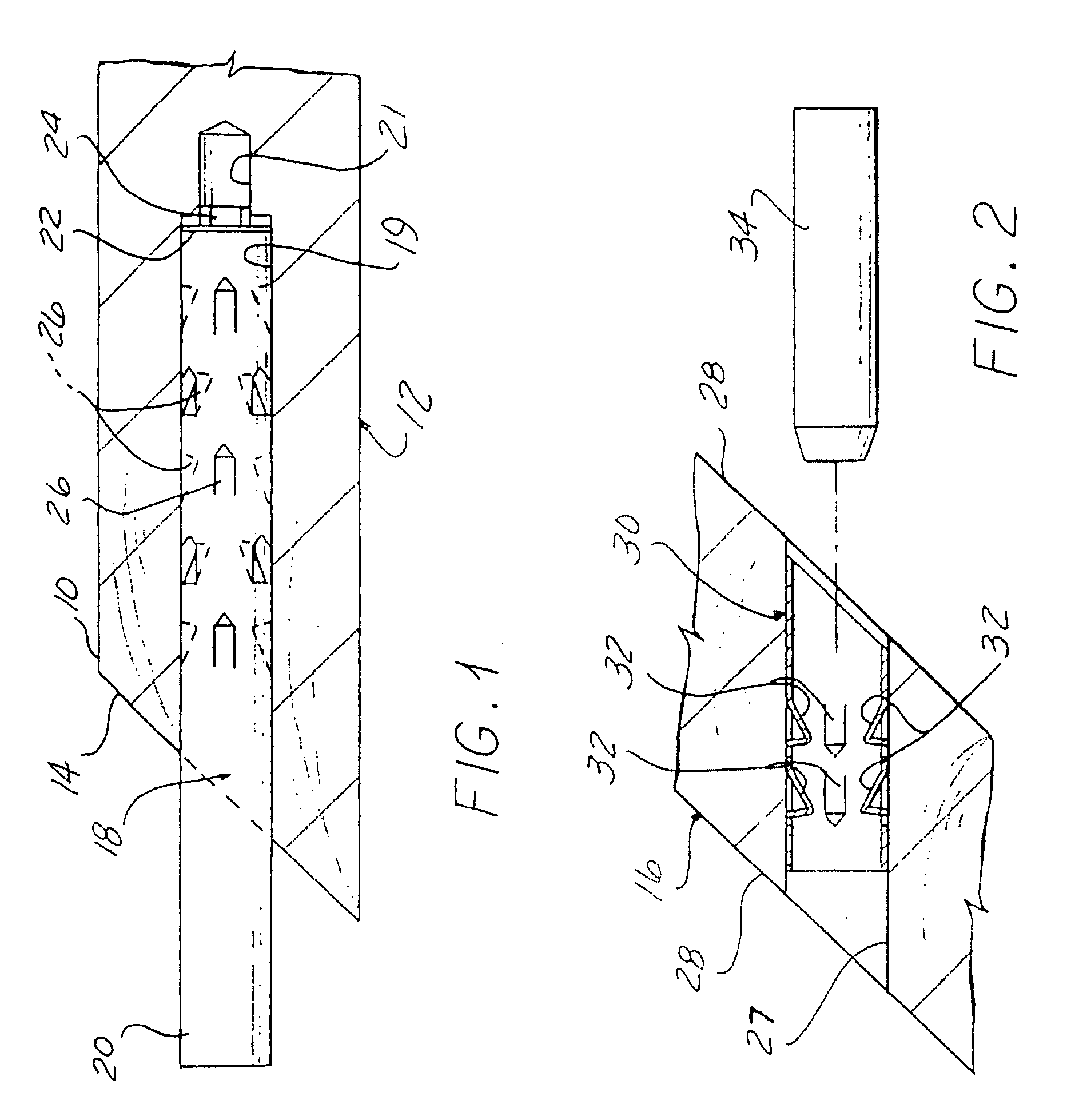
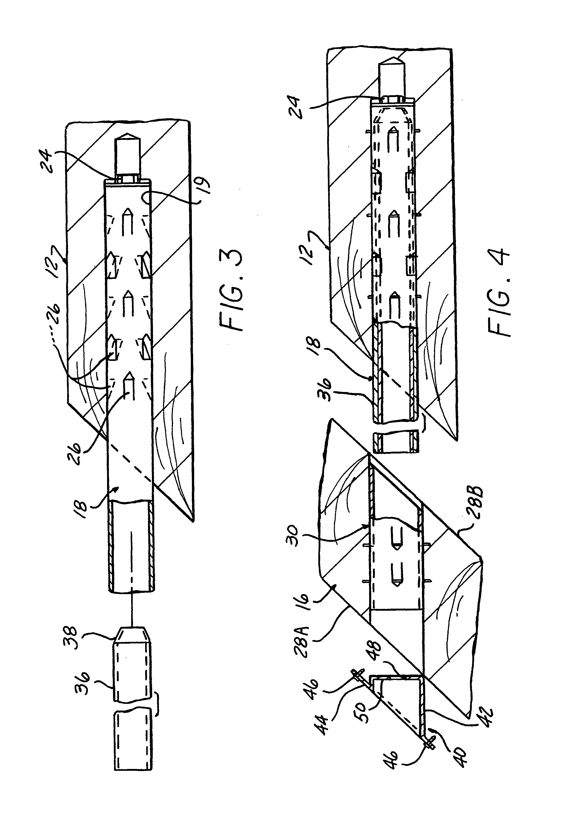
[0039]Referring to the drawings, and particularly FIG. 1, an end 10 of a first wood member 12 such as a log, has the face 14 cut at an angle corresponding to the angle of a joint to be made with a second wood member 16 (FIG. 2).

[0040]A hole 19 is drilled into the face 14 in a direction aligned with the longitudinal axis of the member 10.

[0041]A first metal sleeve 18, preferably of steel which is galvanized or otherwise rust protected is pressed into the hole 19.

[0042]The sleeve 18 is longer than the hole 19 so that a substantial segment 20 thereof protrudes out of the h...


PUM

PropertyMeasurementUnit
diameteraaaaaaaaaa
holding poweraaaaaaaaaa
strengthaaaaaaaaaa

Abstract

A connector and method for joining one end of a first wood member such as a wood log or beam to a side of a second wood member involving metal sleeves secured in aligned holes in a respective member with a protruding one of the sleeve slidable into the other sleeve. A bolt is threaded into an internally threaded element on the inner end of the sleeve in the first member and advanced to pull the members together. The sleeves are secured in the holes with spike features driven out into the surrounding wood. Alternatively, a tee connector has a plate portion fitting into a slot extending through aligned holes in the plate and one end of the first member. A cross plate is held against the one side of the other member with thread fasteners.

Description

CROSS REFERENCE TO RELATED[0001]This application claims the benefit of U.S. provisional application No. 60 / 590,874 filed on Jul. 23, 2004.BACKGROUND OF THE INVENTION[0002]This invention concerns joinery and more particularly joining one end of a member such as a timber beam or log to the side of another member.[0003]Such connections have heretofore been made by mortise and tenon joints or other joints involving shaping of the members themselves, by metal connectors, by lag screws or bolts, etc. For large member joints, screw threads in wood or other soft material have insufficient holding power.[0004]All of these prior methods have disadvantages, primarily in the cost or time involved in making the joint due to the need to machine the wood or to install costly, complicated connectors or result in a joint of inadequate strength.[0005]Many such joints use components which are conspicuously exposed, to be unsightly.[0006]It is the object of the present invention to provide a joint betw...

Claims


Application Information

Patent Timeline
Patent Type & Authority Patents(United States)
IPC IPC(8): B25G3/20F16B2/00F16B7/04
CPCF16B13/025F16B13/126E04B1/2604Y10T403/3933Y10T29/49948Y10T403/3946Y10T403/7051Y10T403/7077Y10T403/3966Y10T403/75Y10T29/49963F16B9/052F16B9/056
Inventor KAUPPILA, RICHARD W.
Owner KAUPPILA RICHARD W
Why Eureka
Try Eureka