Reflecting wave generator apparatus and method

a wave generator and wave generator technology, applied in the field of wave generators, can solve the problem that machines which work in water environments tend to require excess maintenan

Active Publication Date: 2010-10-19
AMERICAN WAVE MACHINES
View PDF29 Cites 37 Cited by
  • Summary
  • Abstract
  • Description
  • Claims
  • Application Information

AI Technical Summary

Benefits of technology

[0006]In one embodiment, a wave generating apparatus has a pool which holds water, the pool having a first and second end, the first end having a back wall, a chamber associated with the pool which is at least partially submerged beneath a water level in the pool and which displaces water in the pool when partially or completely filled with gas, a gas supply connected to the chamber for at least substantially filling the chamber with gas, and a vent valve which releases gas from the chamber, whereby the water level in the pool drops suddenly in the vicinity of the reservoir as the gas is vented from the chamber. This creates a depression or wave trough in the water surface. Gravity changes the water particle motion from downwards to rearwards, which induces water to flow towards the back wall in a rearward surge and reflect off of it. The back wall is positioned and shaped so as to produce the reflected wave. The water rises up the back wall, creating the peak which travels forward following the trough and completing a single circular motion cycle. The trough component leads the peak component as the wave travels forward through the body of water. With this apparatus, the wave starts at a location away from the wave generator, and then moves toward the generator, whereupon it is reflected back into the pool. This results in a more natural wave.
[0007]In one embodiment, the chamber is a submerged or partially submerged, air filled bladder located in a rear portion of the pool. The bladder has an air inlet valve and an exhaust valve, or a single two-way valve for both air supply and venting purposes. Air is released rapidly from the bladder through the exhaust valve, which causes the main pool water to fall rapidly at the location of the bladder, forming a trough. The water moves rearward and reflects against the back wall, creating an upward motion followed by forward motion. Together, these effects create a wave which is similar to the deep water waves with its circular motion. This cycle can be augmented by rapidly introducing pressurized air through the air inlet valve timed to increase the height of the wave as it reflects off the back wall of the pool. This augmentation produces a larger wave.
[0008]In another embodiment, at least one rear chamber in the pool has an underwater passageway communicating with water in the pool, a gas inlet valve which supplies gas to the chamber, and a vent valve for releasing gas from the chamber. In one wave generating method, air is supplied slowly to the chamber so as to drive water out of the rear chamber, and then air is released rapidly via the vent valve, allowing the main pool water to fall rapidly, making the trough part of a wave first. The water moves rearward and reflects against the back wall, creating an upward motion followed by forward motion, completing the circular motion cycle and creating the wave. Together these create a wave which is much more similar to the deep water waves with its circular motion. In one embodiment, a valve communicating with a pressurized gas source may be opened to rapidly force water out of the chamber and increase the height of the wave peak. In another embodiment, a valve communicating with a vacuum source may be opened in order to apply vacuum to the chamber and increase the rate of exhaust of a gas such as air from the chamber. This lifts the water higher in the chamber and creates a deeper trough to the wave. In a third embodiment, vacuum and pressure are combined in phase to amplify the wave.

Problems solved by technology

Machines which work in a water environment tend to require excess maintenance.
This machine suffers from the problem that the wave so generated is turbulent at first and thereby requires a long wave pool to form into a deep-water wave with an organized circular motion.

Method used


Image

  • Reflecting wave generator apparatus and method
  • Reflecting wave generator apparatus and method
  • Reflecting wave generator apparatus and method

Examples


Embodiment Construction

[0023]Certain embodiments as disclosed herein provide for a reflecting wave generating apparatus for a wave pool.

[0024]After reading this description it will become apparent to one skilled in the art how to implement the invention in various alternative embodiments and alternative applications. However, although various embodiments of the present invention will be described herein, it is understood that these embodiments are presented by way of example only, and not limitation.

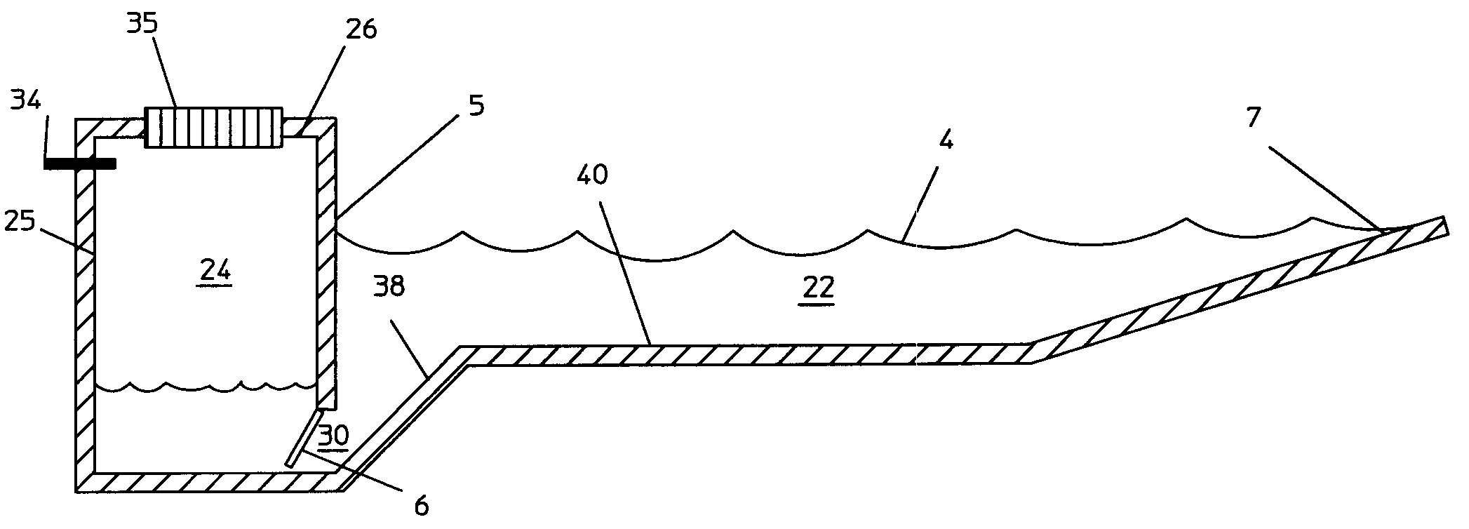
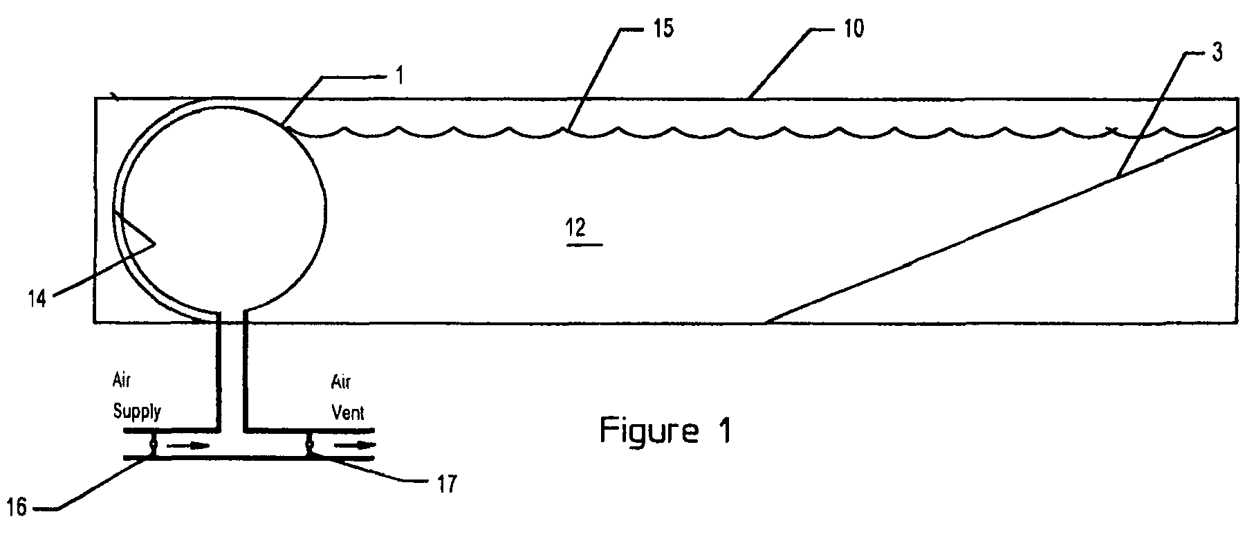
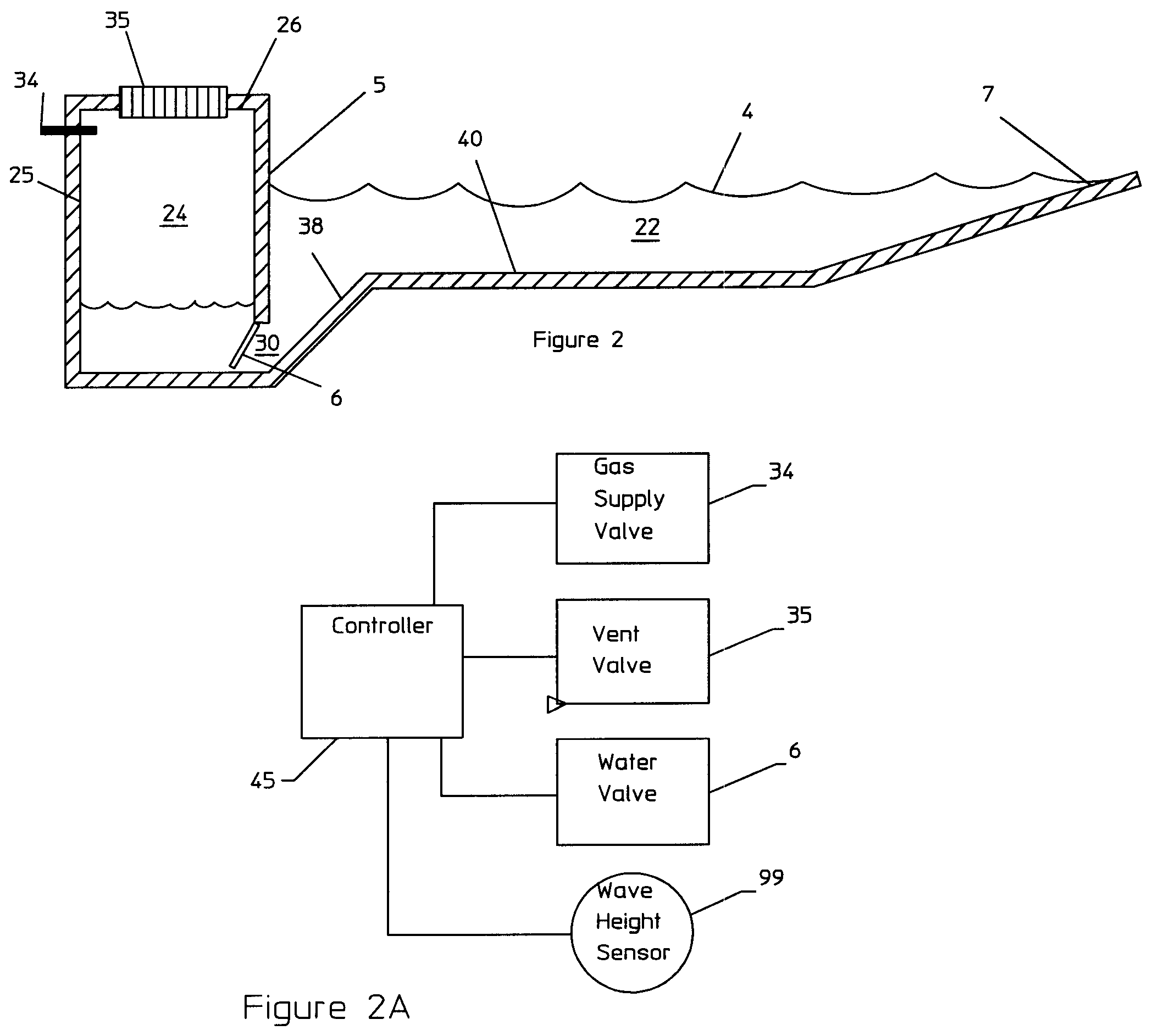
[0025]FIG. 1 illustrates a first embodiment of a wave generator apparatus which comprises a pool or container 10 which contains a body 12 of water, and a collapsible bladder 1 which contains a gas such as air located at one end of the chamber, adjacent a curved, wave reflecting wall 14. The bladder 1 is secured to the floor of the pool. When inflated as in FIG. 1, the bladder is partially or completely submerged beneath the water level 15 of the body of water. The floor of the pool has an upwardly inclined por...


PUM


Abstract

A wave generating apparatus and method in which a chamber is at least partially submerged beneath a body of water in a pool and is connected to a gas supply for at least partially filling the chamber with gas, displacing water in the vicinity of the chamber. A vent valve is arranged to vent gas rapidly from the chamber so that the water level in the vicinity of the chamber falls, forming a wave trough. A wave reflecting wall is positioned in the pool adjacent the chamber and in the vicinity of the wave trough formation so as to reflect the wave away from the chamber and across the body of water. The chamber may have a flexible wall for displacing water or may be a rigid chamber communicating with the water through a submerged passageway. This apparatus forms a wave trough followed by a wave peak which travels across the pool.

Description

RELATED APPLICATION[0001]The present application claims the benefit of co-pending U.S. provisional patent application No. 60 / 849,177 filed Oct. 4, 2006 and co-pending U.S. provisional patent application No. 60 / 904,202 filed Mar. 1, 2007, the contents of each of which is incorporated herein by reference in its entirety.BACKGROUND[0002]1. Field of the Invention[0003]This invention relates generally to wave generators for making waves in a pool of water or other liquid for recreational or scientific purposes.[0004]2. Related Art[0005]Existing systems for making waves use water pumping or rapid air pumping machines to primarily push water to create the waves. Machines which work in a water environment tend to require excess maintenance. In U.S. Pat. No. 5,098,222, a device is described which avoids water contact by pumping air instead of water. This machine suffers from the problem that the wave so generated is turbulent at first and thereby requires a long wave pool to form into a deep...

Claims


Application Information

Patent Timeline
Patent Type & Authority Patents(United States)
IPC IPC(8): E02B3/00
CPCE04H4/0006
Inventor MCFARLAND, BRUCE C.HARRINGTON, STEVEN M
Owner AMERICAN WAVE MACHINES
Why Eureka
Try Eureka