
Temperature controller for structure

a technology of temperature controller and structure, applied in the field of temperature controller, can solve the problems of difficult precise inspection, undesirable contact of foreign objects, and lowering inspection efficiency

Inactive Publication Date: 2010-10-19
CANON KK
View PDF11 Cites 2 Cited by
  • Summary
  • Abstract
  • Description
  • Claims
  • Application Information

AI Technical Summary

Benefits of technology

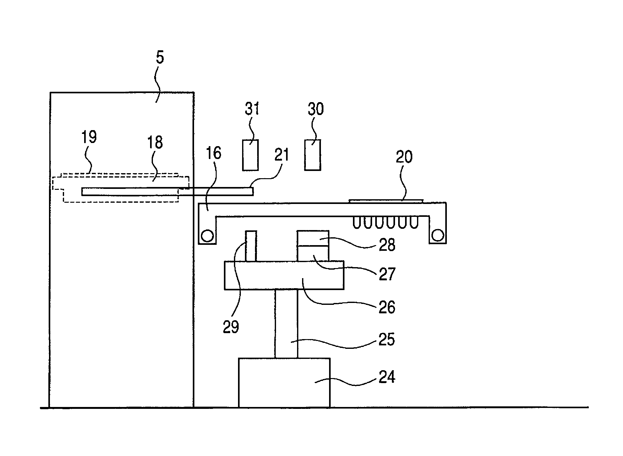
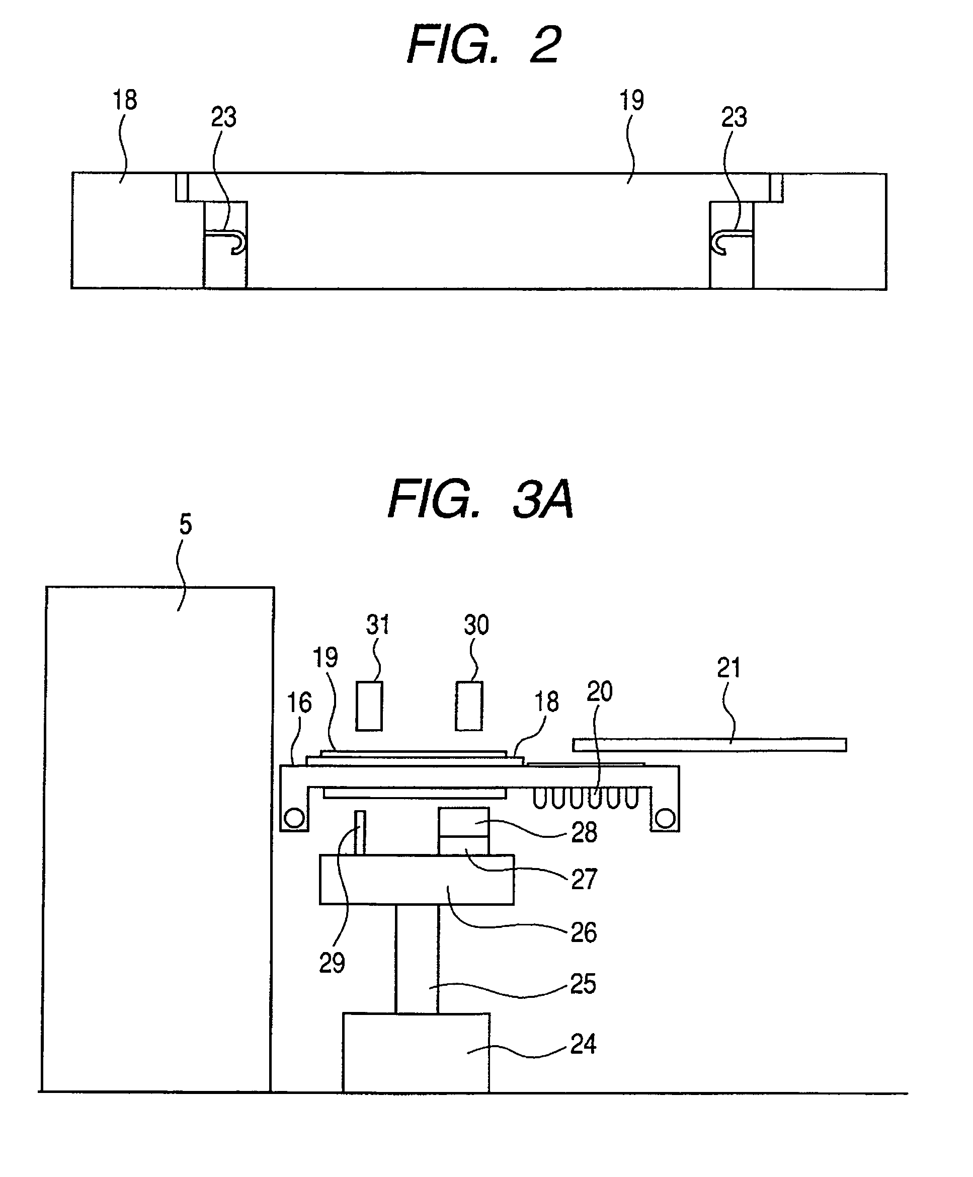
[0025]According to the present invention, a first structure and a second structure are held in such a manner that inclination of a second flat face of the second structure relative to a first flat face of the first structure can be varied. Thereby, the first structure, when pressure is applied thereto, is brought surely into face-to-face contact with the second flat face of the second structure following the inclination of the second flat face of the second structure. Further, a supporting means are provided to be in contact with the portion of the first structure other than the first flat face to keep the posture of the first structure to some extent with dynamic balance. Thereby, the pressure is uniformly applied to the contact interface to enable sufficient heat conduction between the first structure and the second structure.

Problems solved by technology

However, the inspection conducted with a probe bared on the surface of the immobilizing member can cause undesirable contact of a foreign object with the base plate of a microarray.
This can cause defect or contamination of the probe, making difficult the precise inspection.
This may lower the efficiency of inspection.
However, in the case where the amount of the reactant is small and occupies only a part of the reaction vessel, the entire reaction vessel need not be temperature-controlled.
In this case, uniform heating of the entire reaction vessel including a portion requiring no temperature control is inefficient in view of the heating efficiency.
When the above prior art technique is employed without modification, the biochemical reaction cassette is held directly by the elastic member, which makes it difficult to control precisely the posture of the biochemical reaction cassette.

Method used


Image

  • Temperature controller for structure
  • Temperature controller for structure
  • Temperature controller for structure

Examples


example

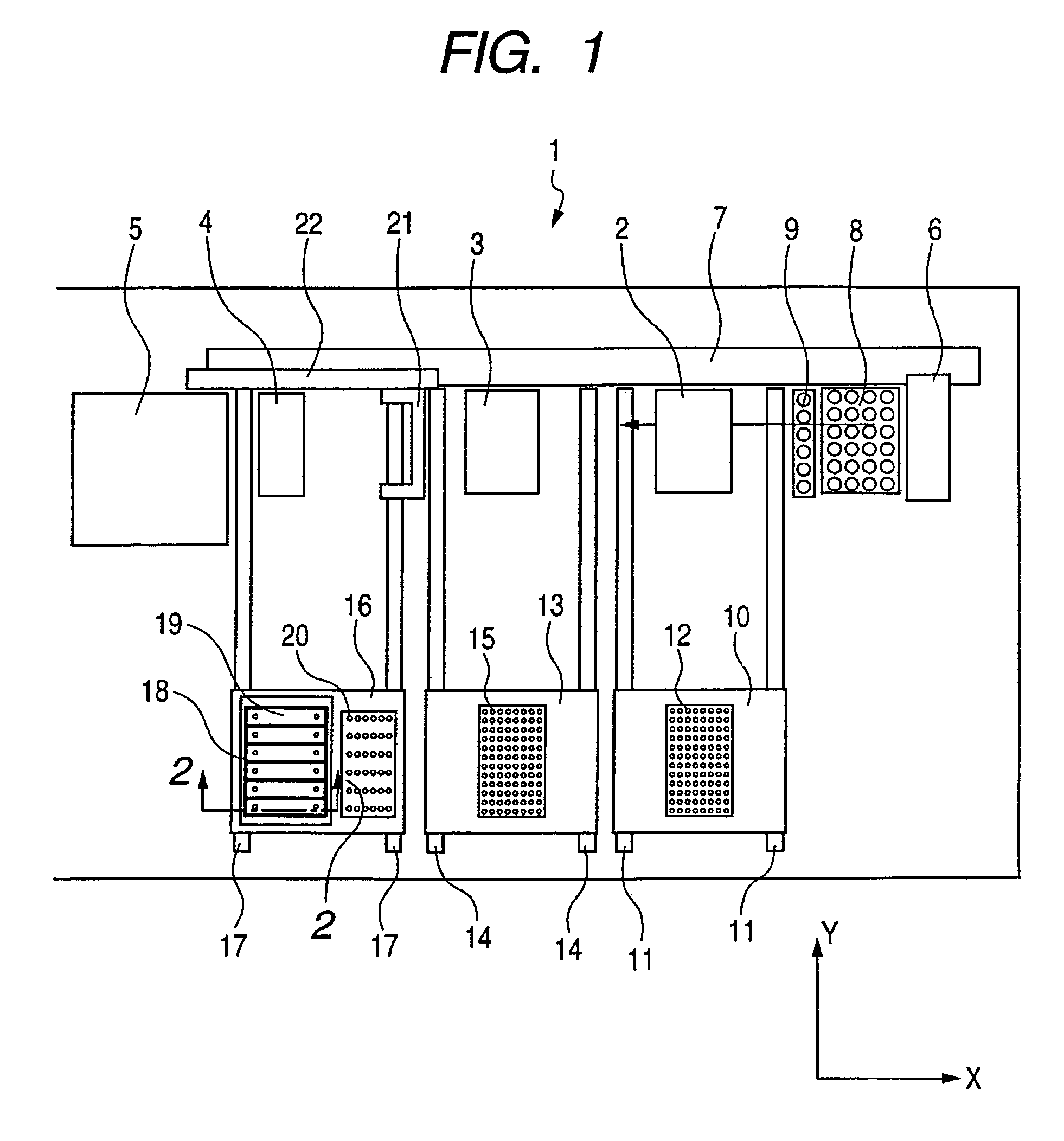
[0063]An example of the temperature controller of the present invention comprising biochemical reaction cassette 19, supporting member 29, Peltier element 27, thermal block 28, pressing mechanism 30, and connecting mechanism 31 is explained in detail by reference to FIGS. 4A to 6.

[0064]FIGS. 4A to 4D illustrate a construction of a biochemical reaction cassette 19. FIG. 4A is a plan view; FIG. 4B is a sectional view taken along line 4B-4B in FIG. 4A; FIG. 4C is a sectional view taken along line 4C-4C in FIG. 4B; and FIG. 4D is a bottom view. The bottom face shown in FIG. 4D and the top face shown in FIG. 4A are counter to each other.

[0065]Biochemical reaction cassette 19 comprises base plate 33 which has a DNA probe fixed thereon capable of bonding specifically to the target nucleic acid, namely a DNA microarray; and housing 32 which encloses the microarray. When the DNA probe is brought into contact with a nucleic acid specimen solution and is brought to a prescribed temperature, th...


PUM

PropertyMeasurementUnit
temperatureaaaaaaaaaa
pressureaaaaaaaaaa
physical featureaaaaaaaaaa

Abstract

A temperature controller for controlling temperature of a first structure having a first flat face comprises a second structure having a second flat face for planar contact with the first flat face, a pressure-applying means for pressing the first structure, a second supporting means for supporting the second structure to be capable of changing inclination of the second flat face, a first supporting means for supporting the first structure by contact with a portion of the first structure other than the first flat face, and a temperature-controlling means, wherein the first structure is supported by pressing the first structure by the pressure-applying means, and the second structure is brought into contact with the temperature-controlling means with interposition of the second supporting means.

Description

BACKGROUND OF THE INVENTION[0001]1. Field of the Invention[0002]The present invention relates to a temperature controller for controlling the temperature of a part of a structure such as a biochemical reaction cassette.[0003]2. Description of the Related Art[0004]For rapid and precise detection of a target nucleic acid in a nucleic acid sample and analysis of the nucleic acid base sequence, various methods are known which utilize a hybridization reaction with a probe carrier. The typical probe carrier for the hybridization reaction is a SNA microarray which immobilizes, on a bead or a glass plate, a probe having a base sequence complementary to the target nucleic acid.[0005]This DNA microarray is promising for medical diagnosis for identifying a pathogen, and for genetic diagnosis for inspecting the physical feature of a patient. For practicing such diagnosis inspection, simplification of the operation is necessary for higher efficiency of the data analysis and examination. However,...

Claims


Application Information

Patent Timeline
Patent Type & Authority Patents(United States)
IPC IPC(8): C12M1/36C12M1/38C12M3/00
CPCB01L3/502B01L7/52B01L2300/0636B01L2300/069B01L2300/0809B01L2300/1805B01L2300/1822B01L2400/049G01N35/028G01N2035/00356
Inventor MUNENAKA, KATSUMI
Owner CANON KK
Learn More