A kind of smd sampling inspection and counting equipment for material tray

An equipment and tray technology, applied in the field of SMD sampling and inventory equipment, can solve the problems of separation of picking and detection processes, limited detection platform, waste of resources, etc. Operation convenience, the effect of vacuum negative pressure structure optimization

Active Publication Date: 2018-01-26
HUAZHONG UNIV OF SCI & TECH
View PDF5 Cites 0 Cited by
  • Summary
  • Abstract
  • Description
  • Claims
  • Application Information

AI Technical Summary

Problems solved by technology

Although some devices capable of detecting SMD trays have been proposed in existing equipment, further research shows that there are still the following major deficiencies: First: the existing equipment often uses the work of carrying out full inspection of SMD trays This mode will obviously bring problems such as low work efficiency and waste of resources; second: in terms of detection methods, existing equipment often uses a vacuum suction head to absorb SMD, and then transfer it to the detection platform for detection, which will cause There are two main defects. On the one hand, the detection platform is limited to a fixed structural configuration, and the types and types of components that can be accurately detected are often relatively small. On the other hand, the picking and testing processes are separated, which will seriously Reduce the overall detection efficiency, especially will directly affect the detection accuracy; third: in many cases in actual working conditions, it is necessary to perform quantitative cutting with high precision and strong applicability while pointing the SMD material tray , but now there are devices that are not able to provide the functional requirements in this regard

Method used


Image

  • A kind of smd sampling inspection and counting equipment for material tray
  • A kind of smd sampling inspection and counting equipment for material tray
  • A kind of smd sampling inspection and counting equipment for material tray

Examples


Embodiment Construction

[0028] In order to make the object, technical solution and advantages of the present invention clearer, the present invention will be further described in detail below in conjunction with the accompanying drawings and embodiments. It should be understood that the specific embodiments described here are only used to explain the present invention, not to limit the present invention. In addition, the technical features involved in the various embodiments of the present invention described below can be combined with each other as long as they do not constitute a conflict with each other.

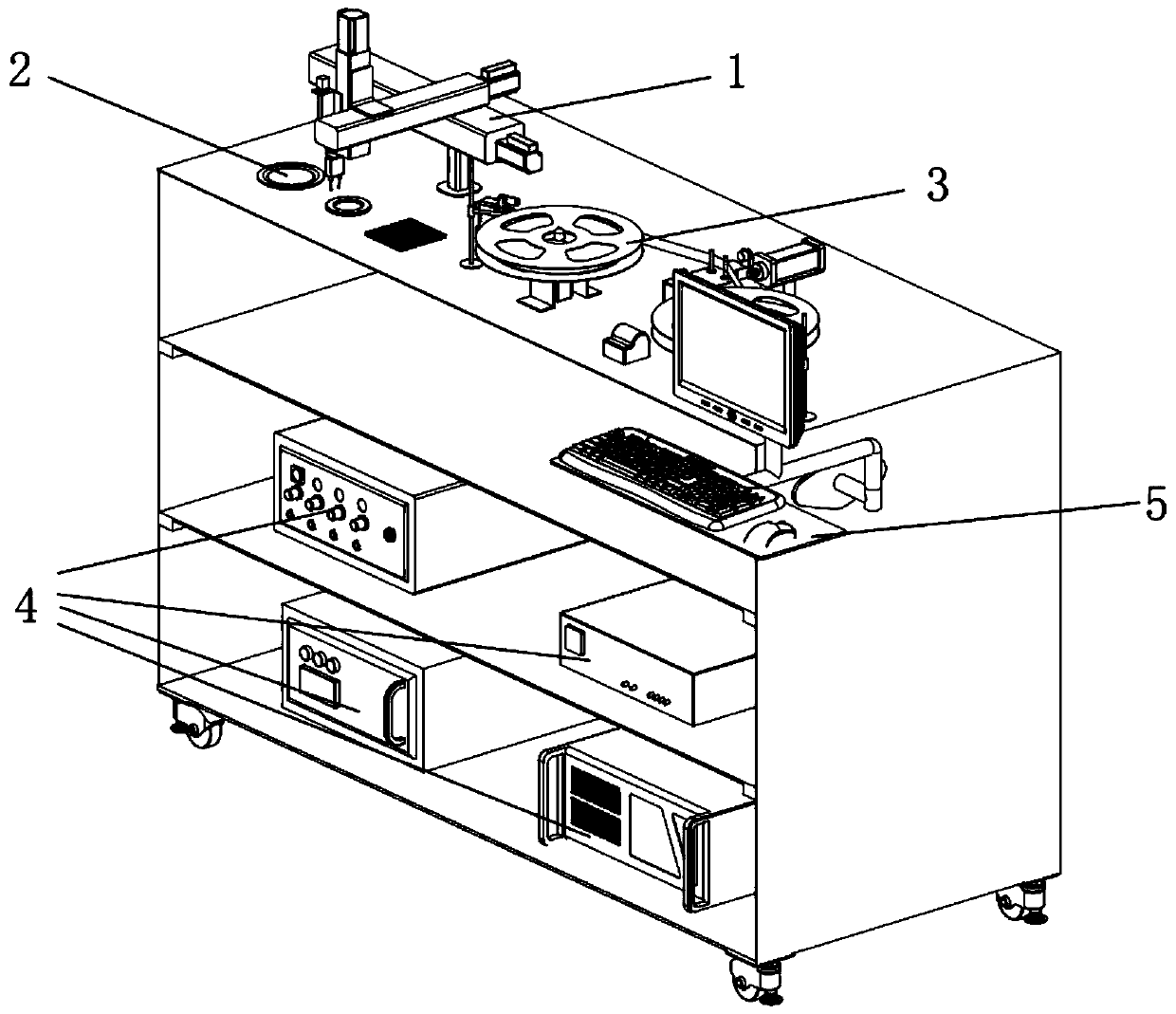
[0029] figure 1 It is a schematic diagram of the overall structure of the SMD tray sampling and testing equipment constructed according to the preferred implementation of the present invention. like figure 1 As shown in , the SMD sampling and counting equipment mainly includes a material pointing module 3, a picking detection module 1, a material filling module 2, and supporting control module...


PUM


Abstract

The invention belongs to the field of related equipment for manufacturing surface mount devices, and discloses tray-oriented SMD sampling and counting equipment. The tray-oriented SMD sampling and counting equipment comprises a material counting module, a pickup detection module, a material holding module, a matched control module and the like, wherein the material counting module is used for achieving conveying and slitting of a material strip and counting of to-be-detected elements; the pickup detection module is used for achieving visual positioning of to-be-detected elements, picking up the to-be-detected elements by a multi-degree-of-freedom manipulator and synchronously achieving the detection function; the material holding module is used for placing the elements before and after detection, and ensuring the accuracy of the positions and the postures of the elements; and the control module is used for achieving automatic control on the complete equipment. Through the tray-oriented SMD sampling and counting equipment, sampling of the elements on an SMD tray can be quickly finished; the sampled elements are recycled; in addition, counting of the elements on the tray can also be quickly and accurately finished; and slitting is selectively carried out under needed working conditions.

Description

technical field [0001] The invention belongs to the field of equipment related to the manufacture of surface mount devices, and more specifically relates to an SMD sampling inspection and counting equipment facing trays. Background technique [0002] With the vigorous development of the electronics industry, in order to realize the miniaturization of electronic products and greatly improve the production efficiency, SMT (Surface Mount Technology, Surface Mount Technology) came into being. The so-called SMT is an electronic assembly technology that installs SMD (Surface Mounted Devices, Surface Mount Devices) on a PCB, and is one of the key technologies for PCB mounting. Compared with traditional electronic component mounting technology, SMT has the characteristics of strong reliability, good high-frequency characteristics, small component size, and automatic production, so it has developed rapidly after entering the 21st century. [0003] However, one of the technical probl...

Claims


Application Information

Patent Timeline
Patent Type & Authority Patents(China)
IPC IPC(8): H05K13/08
CPCH05K13/08
Inventor 陈建魁刘腾蒋博
Owner HUAZHONG UNIV OF SCI & TECH
Why Eureka
Try Eureka