
Steel-frame cutting method and device

a cutting method and a technology for steel frames, applied in auxillary welding devices, soldering devices, building repairs, etc., can solve the problems of reducing efficiency, affecting work efficiency improvement, and inconstant portage to the surface of steel frames, so as to achieve efficient cutting of steel frames and short time

Pending Publication Date: 2021-07-15
KOBELCO CONSTR MASCH CO LTD
View PDF0 Cites 0 Cited by
  • Summary
  • Abstract
  • Description
  • Claims
  • Application Information

AI Technical Summary

Benefits of technology

The invention provides a new cutting method for efficient cutting of steel frames, which involves moving a cutting torch in a perpendicular direction to the cutting surface of the steel frame and applying flame and cutting oxygen to cut the frame. However, this method may result in cutting defects on certain parts of the cutting surface, requiring revision of the torch position and flame / oxygen supply. To address this problem, the inventors conceived a method where the torch moves in a reverse direction to efficiently cut the uncut parts of the cutting surface before the temperature of the steel frame drops. This results in improved work efficiency and efficiency of the cutting process.

Problems solved by technology

However, the new cutting method, in which the distance from the fire port to the surface of the steel frame inconstant, is likely to involve a cutting defect in a part of the cutting surface, the part being away from the fire port or hidden behind another portion as seen from the torch, or the like, depending on the size and shape of the cutting surface of the steel frame.
Cutting the part thus having failed to be cut may require greatly changing the orientation and position of the large cutting torch and re-supplying flame and cutting oxygen from the opposite side, which rather has a possibility of hindering the work efficiency improvement.
Moreover, the temperature of the steel frame that has been heated is lowered during the change of the orientation and position of the cutting torch, which further decreases the efficiency.

Method used


Image

  • Steel-frame cutting method and device
  • Steel-frame cutting method and device
  • Steel-frame cutting method and device

Examples


first embodiment

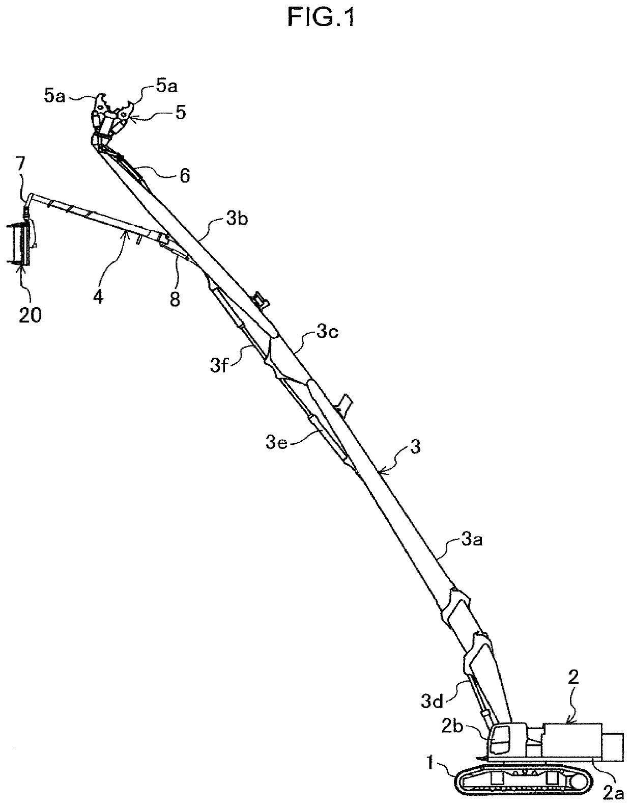
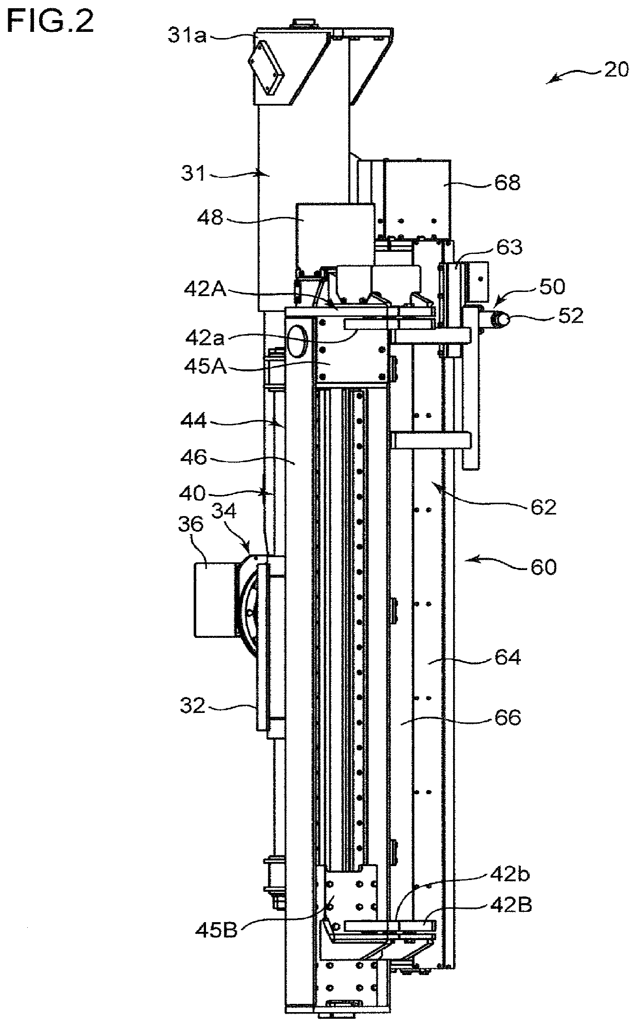
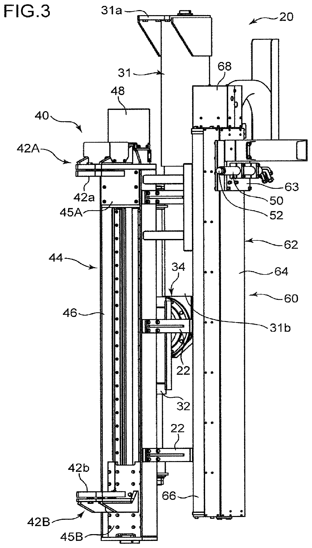
[0062]The cutting apparatus according to the present invention further includes a controller 70, a plurality of sensors, and an input device 84 as shown in FIG. 10, in addition to the cutting apparatus body 20.

[0063]The controller 70 is an arithmetic control device made of, for example, a microcomputer, mounted on the upper slewing body 2 and electrically connected to the cutting apparatus body 20 to control the gripping motion and the cutting motion of the cutting apparatus body 20.

[0064]The plurality of sensors generate electrical signals as detection signals as to the operational state of the cutting apparatus body 20 and input them to the controller 70. Specifically, the plurality of sensors include gripping contact sensors 81A, 81B, gripping position sensors 82A, 82B and a cutting position sensor 83.

[0065]The gripping contact sensors 81A, 81B are provided to the first and second gripping members 42A, 42B, respectively, to detect whether or not the gripping surfaces 42a, 42b of ...

second embodiment

[0095]Next will be described the present invention with reference to FIGS. 13 and 14.

[0096]FIG. 13 shows a functional configuration and input / output signals with respect to the controller 70 according to the second embodiment. Although the controller 70, similarly to the same according to the first embodiment, includes the gripping control section 71, a position setting section 72, a cutting control section 73 and a mode determination section 74, a mode selection switch 85 is connected to the controller 70, in addition to or in place of the input device 84.

[0097]The mode selection switch 85 functions as a selection input unit for allowing a selection command input operation to be applied to the mode selection switch 85 by an operator. The selection command input operation is an operation applied to the mode selection switch 85 to input a selection command to the controller 70, and the selection command is a command for selecting the cutting control mode of the cutting control sectio...

third embodiment

[0100]Next will be described the present invention with reference to FIGS. 15 to 17.

[0101]FIG. 15 shows a functional configuration and input / output signals of the controller 70 according to the third embodiment. Although the controller 70 includes a gripping control section 71, a position setting section 72, a cutting control section 73, and a mode determination section 74, similarly to the controller 70 according to the first embodiment, the cutting apparatus according to the third embodiment includes a cutting condition sensor 86 in addition to a plurality of sensors included in the cutting apparatus according to the first and second embodiments, the cutting condition sensor 86 being connected to the controller 70.

[0102]The cutting condition sensor 86 is a cutting condition detector, configured to detect the cutting condition of the cutting surface produced by the movement of the cutting torch 50 from the cutting start position to the first cutting end position. The cutting condit...


PUM


Abstract

A method and an apparatus efficiently and reliably cut a steel frame. The cutting method includes locating a cutting torch apart from the steel frame held by a holding device in a direction along a cutting surface, moving the cutting torch from a cutting start position to a first cutting end position in a first feed direction perpendicular to a supply direction along the cutting surface, while applying a flame from a fire port of the cutting torch in the supply direction and supplying cutting oxygen to thereby cut a part of the cutting surface, stopping the cutting torch at the first cutting end position and thereafter cutting an uncut part by moving the cutting torch from the first cutting end position in a second feed direction opposite to the first feed direction.

Description

TECHNICAL FIELD[0001]The present invention relates to a method and an apparatus for cutting a steel frame made of, for example, H-shaped steel or a square pipe, by use of a cutting torch.BACKGROUND ART[0002]Conventionally, as a method and an apparatus for cutting a steel frame using a cutting torch, those described in Patent Document 1 are known. The apparatus includes a clamp for gripping a steel frame of the steel frame, and moving means for moving the cutting torch along the surface while keeping the fire port of the cutting torch closer to the surface. The gripping of the steel frame and the transfer of the cutting torch by the clamp and the moving means are performed through a remote operation.[0003]The above method of thus moving the fire port of the cutting torch along the surface of the steel frame while keeping the fire port close to the surface takes a long time to complete the cutting. This markedly hinders the improvement of the work efficiency.CITATION LISTPatent Litera...

Claims


Application Information

Patent Timeline
IPC IPC(8): B23K7/00B23K37/04B23K7/10
CPCB23K7/003B23K2101/24B23K7/10B23K37/0435E04G23/08B23K2101/28B23K37/0294B23K2103/04
Inventor YAMASAKI, TAKANORIYAMASHITA, KOICHIHOSAKA, YOSHINOBUFUJITA, TSUGUHITO
Owner KOBELCO CONSTR MASCH CO LTD
Learn More