
Collision avoidance for vehicle control systems

a technology of vehicle control system and collision avoidance system, which is applied in the direction of anti-collision system, aircraft stabilisation, navigation instruments, etc., can solve the problems of high cost of conventional avoidance system, inability to integrate such a system on smaller vehicles, and even greater potential for collisions

Active Publication Date: 2010-10-19
L 3 COMM CORP
View PDF50 Cites 35 Cited by
  • Summary
  • Abstract
  • Description
  • Claims
  • Application Information

AI Technical Summary

Benefits of technology

The patent describes a way to use a sensor to scan for potential collisions with an aircraft and determine if it is on a course to enter within a certain distance of the potential object. The system then alters the course of the aircraft to avoid the collision. The technical effect is to provide a way for the aircraft to autonomously or semi-autonomously control its own course to avoid collisions.

Problems solved by technology

These types of conventional avoidance systems are very expensive.
Therefore, integrating such a system on smaller vehicles is not entirely feasible.
The potential for collisions is even greater in the context of unmanned vehicle systems.
Although the ground control station enables some degree of controlled flight, generally, UAVs lack the ability to scout out their surrounding airspace and watch for incoming obstacles.
Even if a UAV is equipped with some sort of forward-looking camera or video capability, the remotely located operator is primarily focused on payload and mission operations and has a limited ability to accurately interpret and analyze video information.
In addition, under the circumstances, a remotely located operator may have a difficult time complying with the FAA rules for flying in civilian airspace.
Currently, UAVs are not allowed to fly in NAS.
In particular, UAVs are not allowed to fly in any air space unless the UAV has received FAA approval.

Method used


Image

  • Collision avoidance for vehicle control systems
  • Collision avoidance for vehicle control systems
  • Collision avoidance for vehicle control systems

Examples


Embodiment Construction

[0014]Much of the description of the present invention will be devoted to describing embodiments in the context of unmanned aerial vehicles (UAV). However, it is to be understood that the embodiments of the present invention pertain to a collision avoidance system and are designed for broad application. The embodiments can be adapted by one skilled in the art to be applied in the context of any of a variety of unmanned and manned vehicles including, but not limited to, airplanes, helicopters, missiles, submarines, balloons or dirigibles, wheeled road vehicles, tracked ground vehicles (i.e., tanks), and the like.

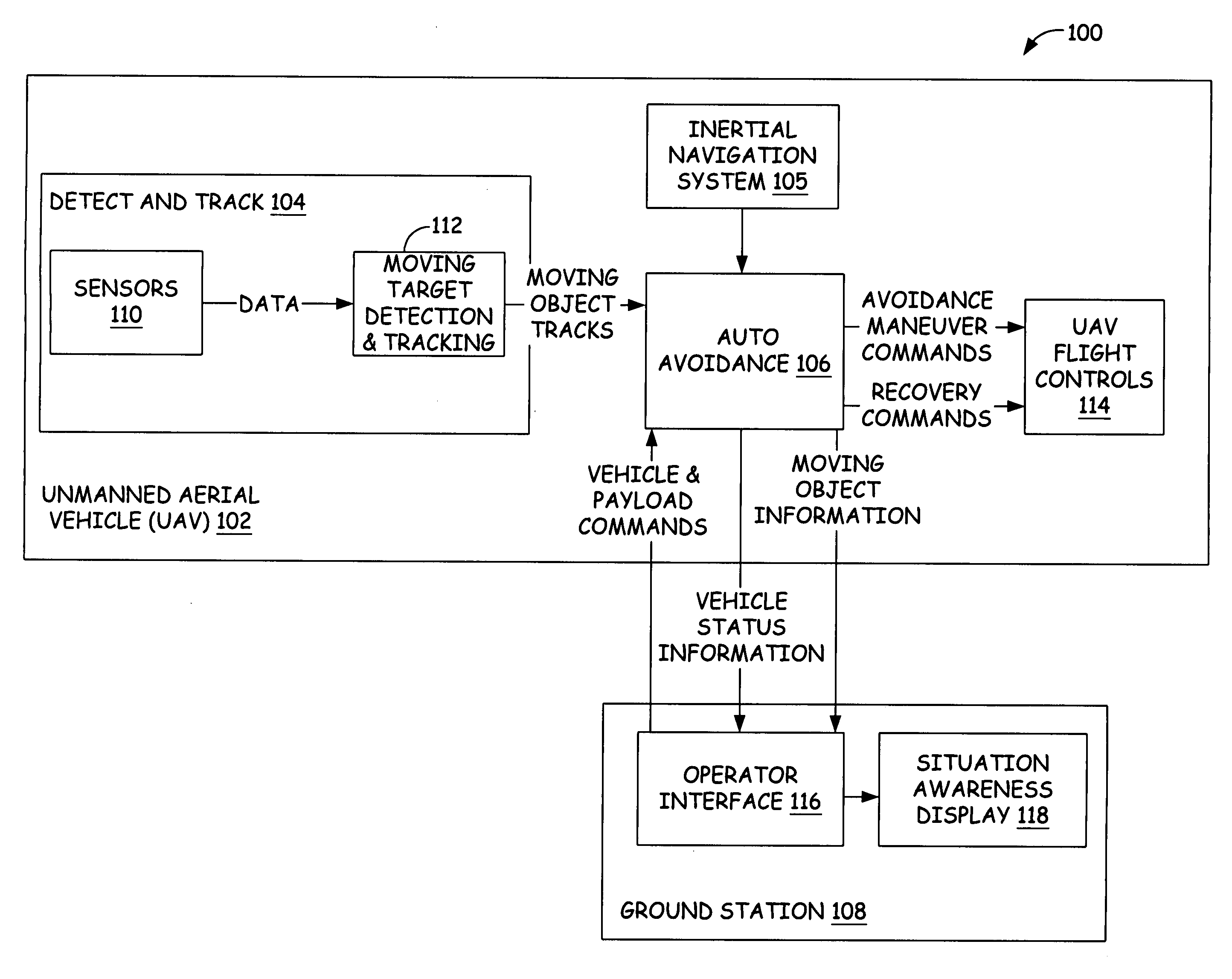
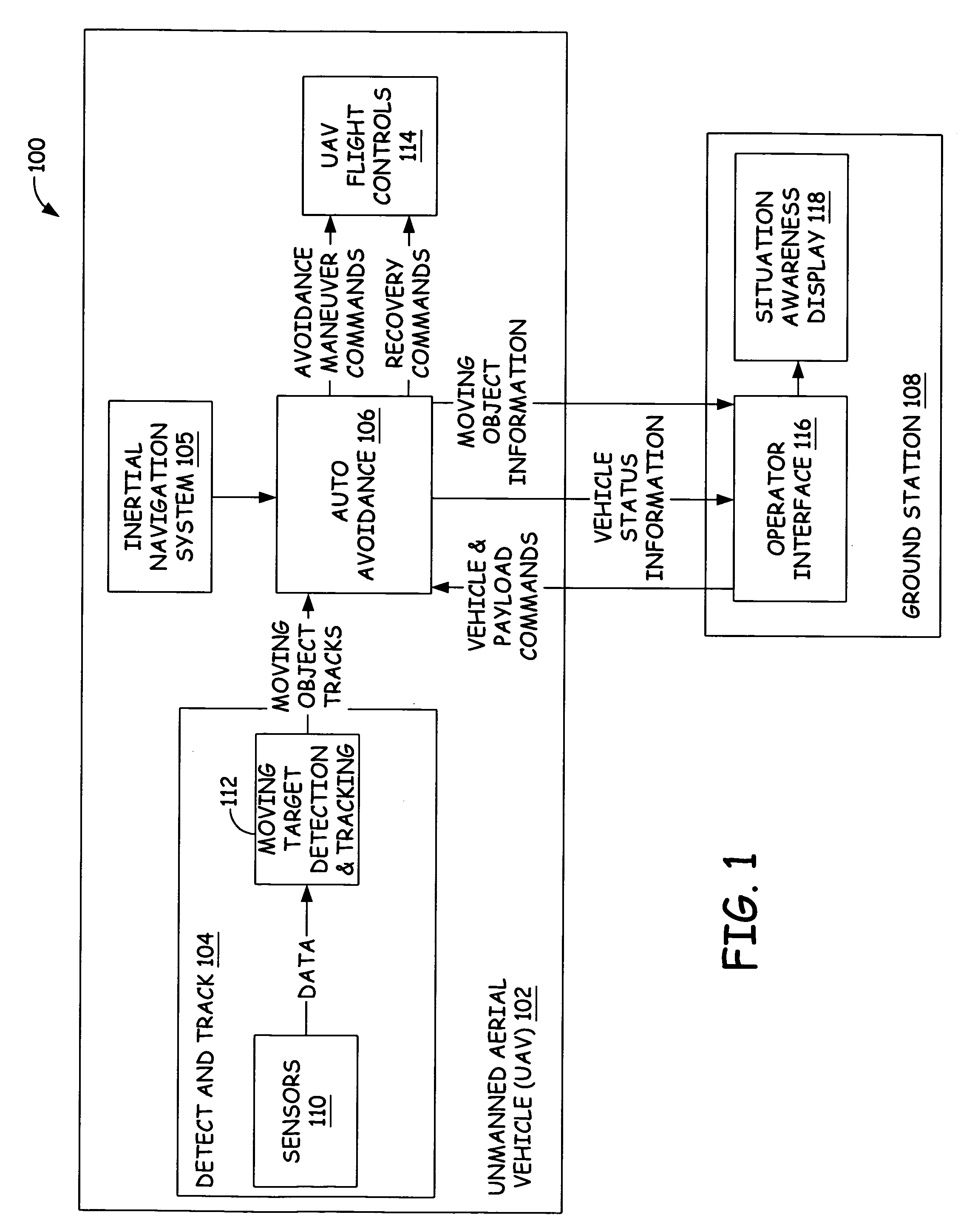
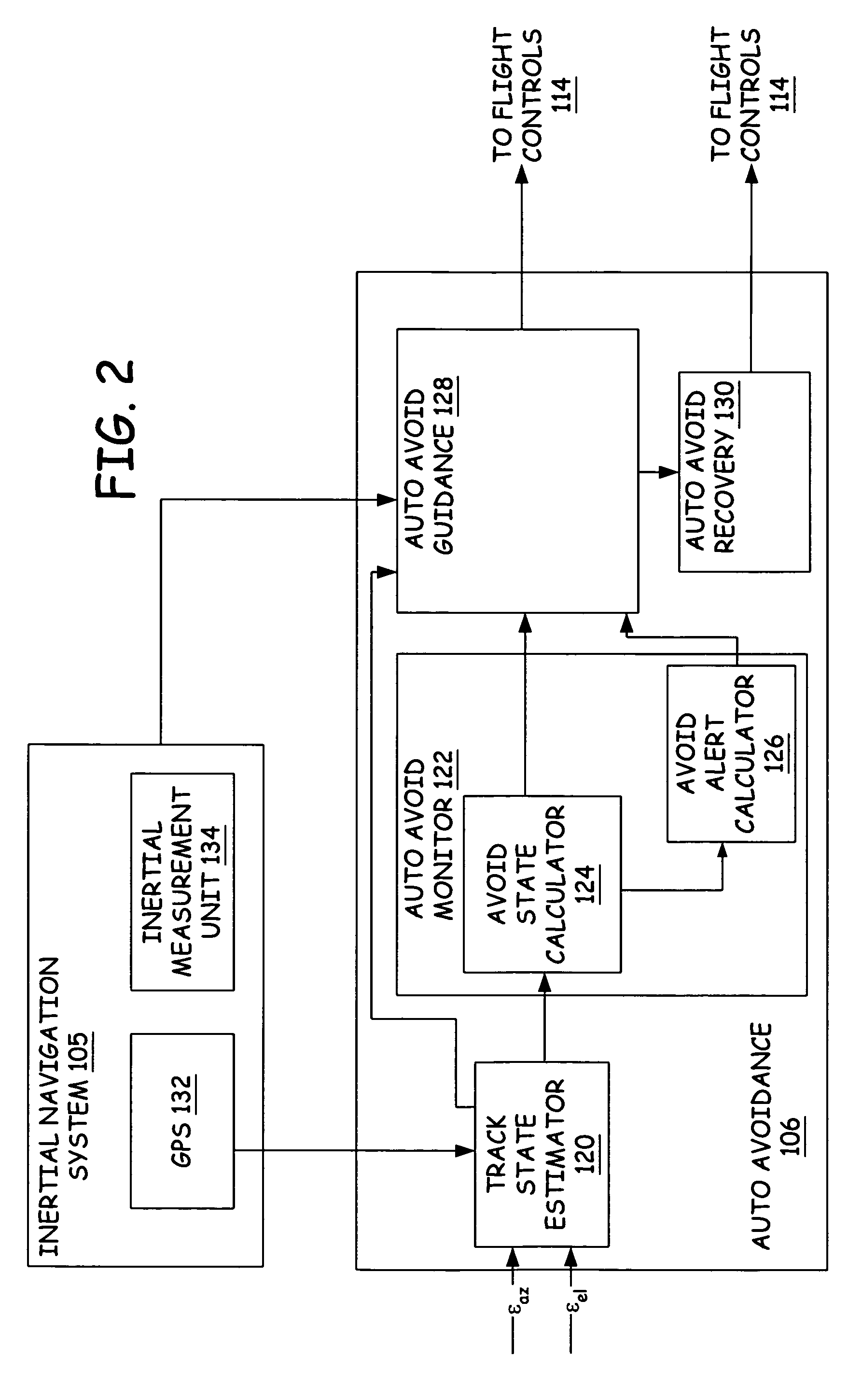
[0015]FIG. 1 illustrates a simplified block diagram of autonomously controlled collision avoidance system 100 as implemented in a UAV 102 in accordance with an embodiment of the present invention. Collision avoidance system 100 includes a detect and track module 104 coupled to an auto avoidance module 106 which is in communication with a ground control station 108, an inertia...


PUM


Abstract

A method and apparatus for at least semi-autonomously controlling a vehicle so as to avoid collisions are provided. A sensor is utilized to scan an area proximate the vehicle for a potential object of collision. The apparatus calculates navigational states of the potential object of collision relative to the vehicle to determine that the vehicle is on a course to enter within a predetermined miss distance relative to the potential object of collision. The apparatus alters the course of the vehicle based on the calculated navigational states.

Description

BACKGROUND OF THE INVENTION[0001]The present invention relates to a collision avoidance system for a vehicle. In particular, the present invention relates to a system that autonomously controls a vehicle to avoid objects of collision.[0002]Many vehicles, such as aircraft vehicles, have systems which use radar for detecting potential objects of collision, such as terrain and other vehicles. Radar can detect potential objects of collision located within a certain proximity to the aircraft vehicle. Upon radar detecting the presence of a potential object of collision, a warning signal is provided to a pilot of the aircraft. The pilot must then analyze the object and determine if action needs to be taken in order to avoid the object. If action needs to be taken, the pilot obeys general aviation and etiquette rules promulgated by the FAA (Federal Aviation Administration) to regulate aircraft vehicle traffic in national air space (NAS).[0003]These types of conventional avoidance systems ar...

Claims


Application Information

Patent Timeline
Patent Type & Authority Patents(United States)
IPC IPC(8): G05D1/00G01S13/50G08G5/04G06F17/00
CPCG08G5/0069G08G5/0086G08G5/045G05D1/101G05D1/106
Inventor DUGGAN, DAVID S.FELIO, DAVID A.ASKEW, CRAIG S.
Owner L 3 COMM CORP
Learn More