
Apparatus for multi-chassis configurable time synchronization

a multi-chassis, configurable technology, applied in the field of industrial controls, can solve the problems of inability to locate all control modules within a single rack or control chassis, inability to perform temporal synchronization of control actions across widely distributed control systems, and inability to provide for synchronizing control events outside of a single control chassis

Active Publication Date: 2010-10-19
ROCKWELL TECH
View PDF23 Cites 33 Cited by
  • Summary
  • Abstract
  • Description
  • Claims
  • Application Information

AI Technical Summary

Benefits of technology

[0015]Another aspect of the invention provides a time synchronization apparatus for synchronizing operation of a first controller with that of a second controller in a control system. The apparatus can be employed in stand-alone controllers, and / or in a module in a control chassis, and can comprise a processor interface for interfacing with a host processor, a transmitter adapted to transmit synchronization information and data to a network in the control system, a receiver adapted to receive synchronization information and data from the network, and a timing system with a clock maintaining an indication of time according to information received from one of the network and the host processor. Still another aspect of the invention provides a synchronization system for synchronizing operation of a first controller with that of a second controller in a control system.

Problems solved by technology

However, conventional CST time-sharing control equipment cannot provide for synchronizing control events outside of a single control chassis.
In these situations, it can be impractical or impossible to locate all the control modules within a single rack or control chassis.
Consequently, it has heretofore been difficult or impossible to perform control actions in temporal synchronization across widely distributed control systems.
In addition, CST timers associated with control chassis backplanes do not provide synchronization of control events performed in stand-alone controllers, such as motor drives.
Moreover, individual CST timers in separate control racks or chassis can drift apart due to the accuracies of their respective timer circuits.

Method used


Image

  • Apparatus for multi-chassis configurable time synchronization
  • Apparatus for multi-chassis configurable time synchronization
  • Apparatus for multi-chassis configurable time synchronization

Examples


Embodiment Construction

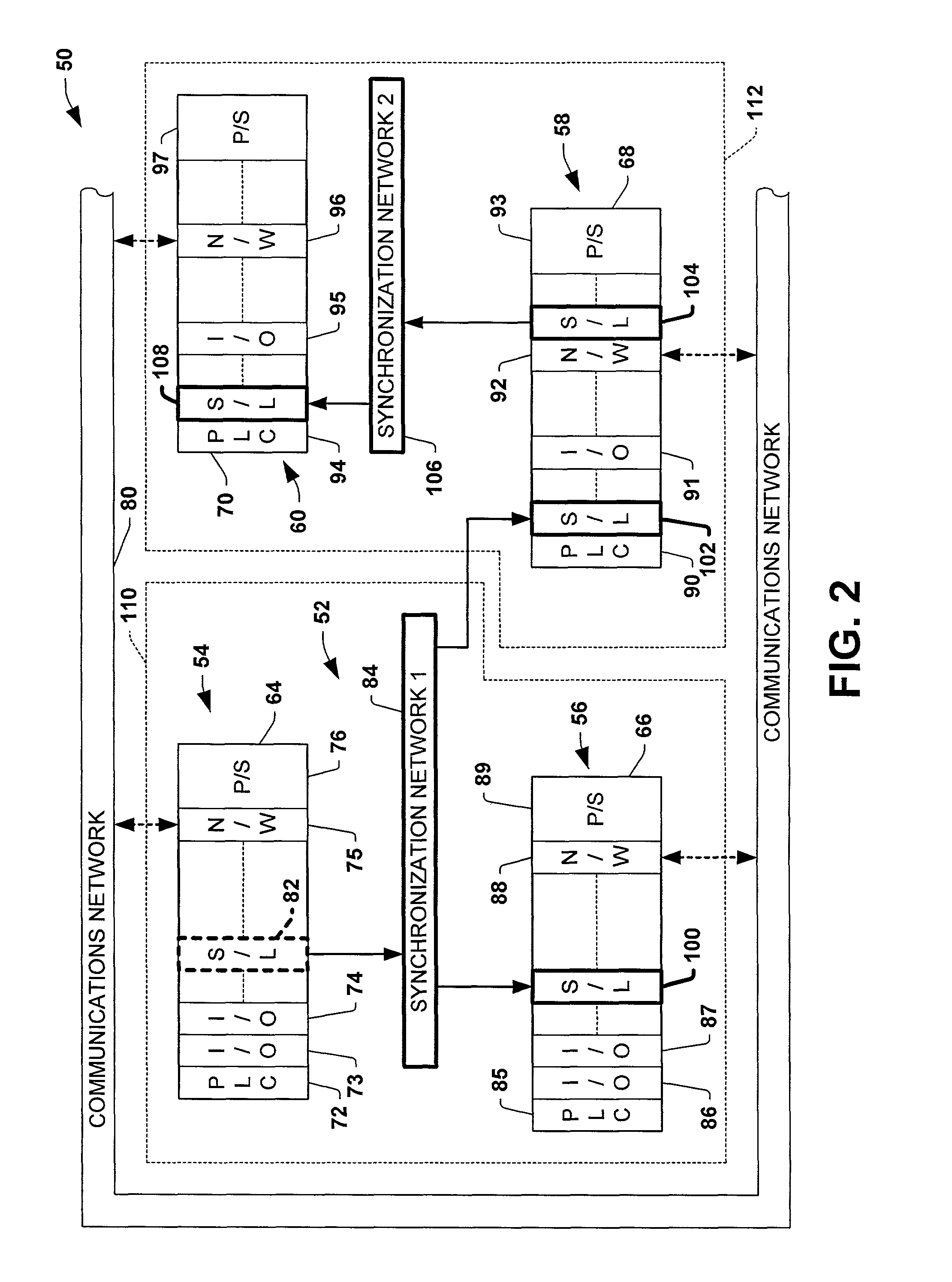
[0052]The various aspects of the present invention will now be described with reference to the drawings, wherein like reference numerals are used to refer to like elements throughout. The invention provides methods and systems for synchronizing controllers in a control system, which overcome or mitigate the problems associated with prior systems and methods. Several exemplary implementations of the various aspects of the invention are hereinafter described. However, it will be appreciated that other implementations are possible within the scope of the appended claims, and that the invention is not limited to the implementations specifically illustrated and / or described herein.

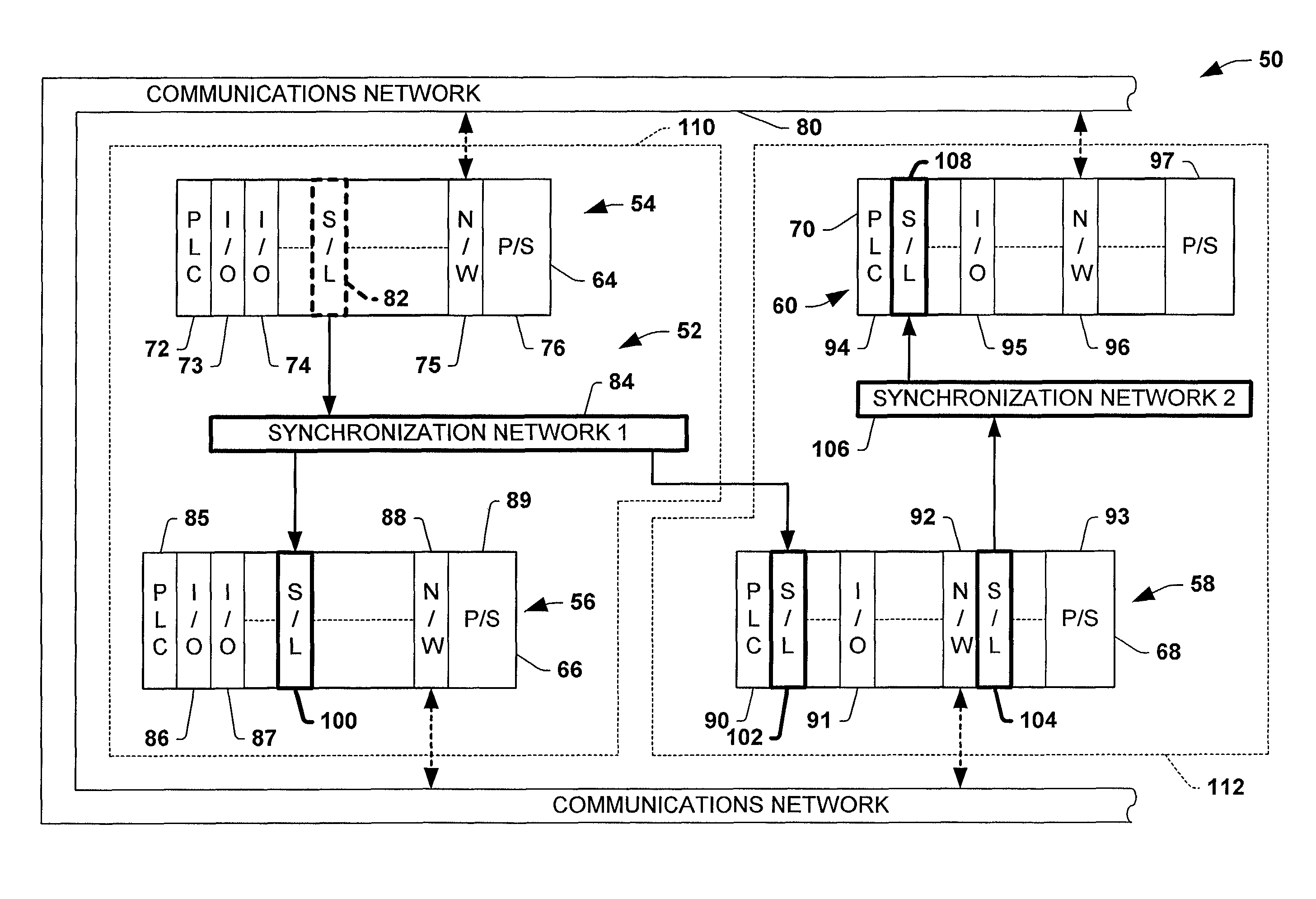
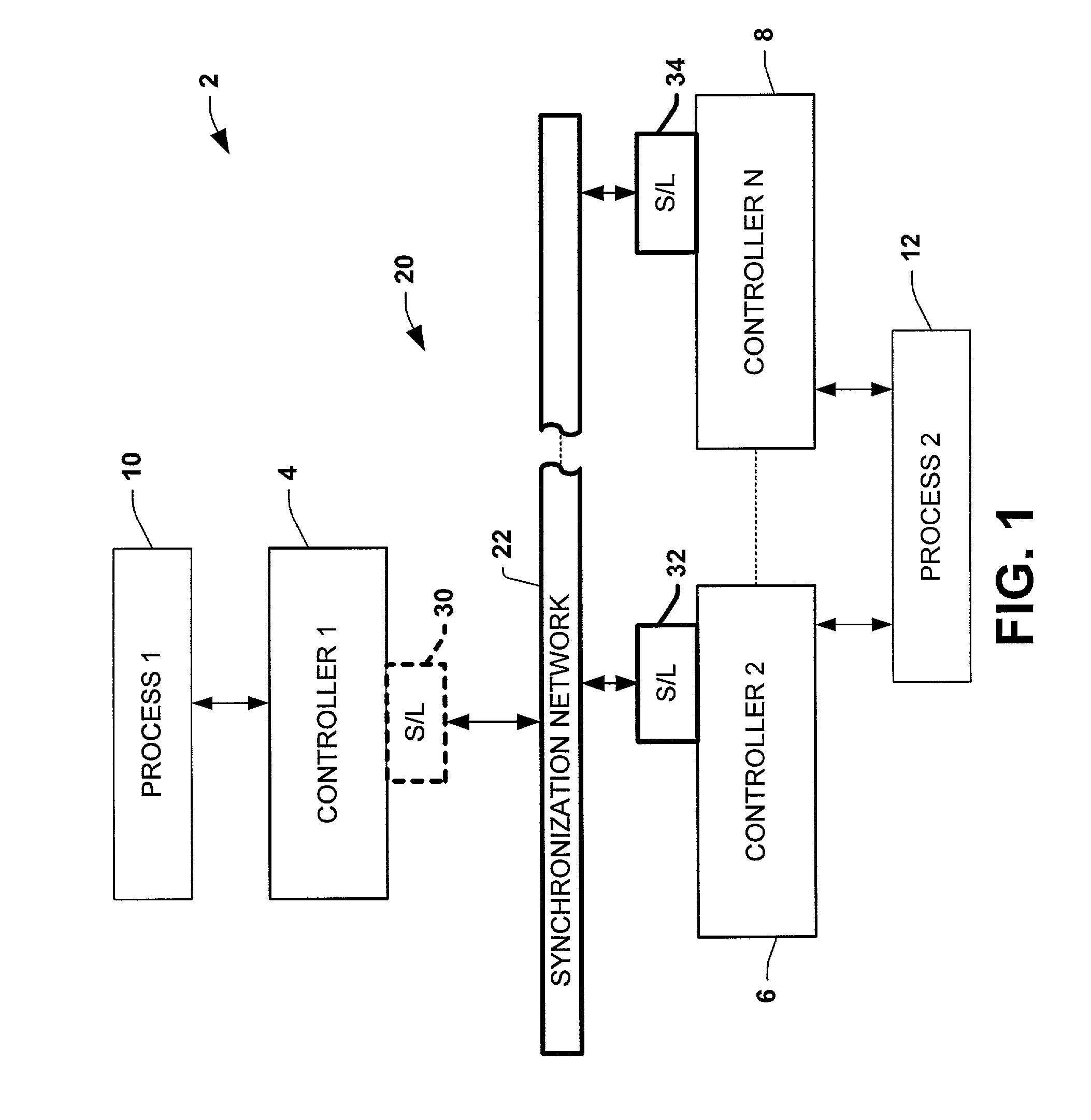
[0053]Referring initially to FIG. 1, an exemplary control system 2 is illustrated having a plurality of controllers 4, 6, and 8 adapted to control one or more processes 10, 12, wherein more than one controller (e.g., controllers 6 and 8) can control portions of the same process (e.g., process 12). The controlle...


PUM


Abstract

Systems and methods are disclosed for time synchronization of operations in a control system. Synchronization networks and devices are provided for transferring synchronization information between controllers in a distributed or localized control system, which is employed in order to allow operation of such controllers to be synchronized with respect to time. Also disclosed are synchronization protocols and hardware apparatus employed in synchronizing control operations in a control system.

Description

TECHNICAL FIELD[0001]The present invention relates to the art of industrial controls and more particularly to apparatus and systems for multi-chassis configurable time synchronization.BACKGROUND OF THE INVENTION[0002]Industrial controllers are special purpose processing devices used for controlling industrial processes, machines, manufacturing equipment, and other factory automation applications. In accordance with a control program or routine, an industrial controller can measure one or more process variables or inputs representative of the status of a controlled process, and change outputs effecting control of the process. The inputs and outputs can be binary, (e.g., on or off), and / or analog assuming a continuous range of values. The control routine can be executed in a series of execution cycles with batch processing capabilities, and can comprise one or more functional units. The measured inputs received from a controlled process and the outputs transmitted to the process can p...

Claims


Application Information

Patent Timeline
Patent Type & Authority Patents(United States)
IPC IPC(8): G06F15/16
CPCH04L12/403
Inventor FLOOD, MARKRUETTY, MARKCACHAT, ANTHONY
Owner ROCKWELL TECH
Learn More