Turbo machine with a rotor which has at least one rotor disk with a bore

a rotor and bore technology, applied in the field of rotor machines, can solve the problems of increasing the restriction of the ability the high load on the rotor disk, and the inability to detect cracks during tests, and achieve the effect of increasing the compressive residual stress

Inactive Publication Date: 2010-10-26
SIEMENS AG
View PDF10 Cites 4 Cited by
  • Summary
  • Abstract
  • Description
  • Claims
  • Application Information

AI Technical Summary

Benefits of technology

[0019]In an advantageous configuration, the bore is arranged centrally, i.e. at the center point of the rotor disk, and/or eccentrically, i.e. at a distance from the center point of the rotor disk. The effects achieved by the convexly curved embodiment are independent of whether the bore is provided cen

Problems solved by technology

In operation, the rotor blades secured to the rotor disk produce huge centrifugal forces, and consequently each rotor disk is exposed to high levels of load.
The ability to detect cracks during the tests is increasingly restricted by the increasing size of rotor disks with a bore or if coarse-grain materials are used.
This causes plastic deformation in the region of the bore, leading to compressive residual stresses.
However, the level of the compressive residual stresses in the disk material is limited by the

Method used


Image

  • Turbo machine with a rotor which has at least one rotor disk with a bore
  • Turbo machine with a rotor which has at least one rotor disk with a bore
  • Turbo machine with a rotor which has at least one rotor disk with a bore

Examples


Embodiment Construction

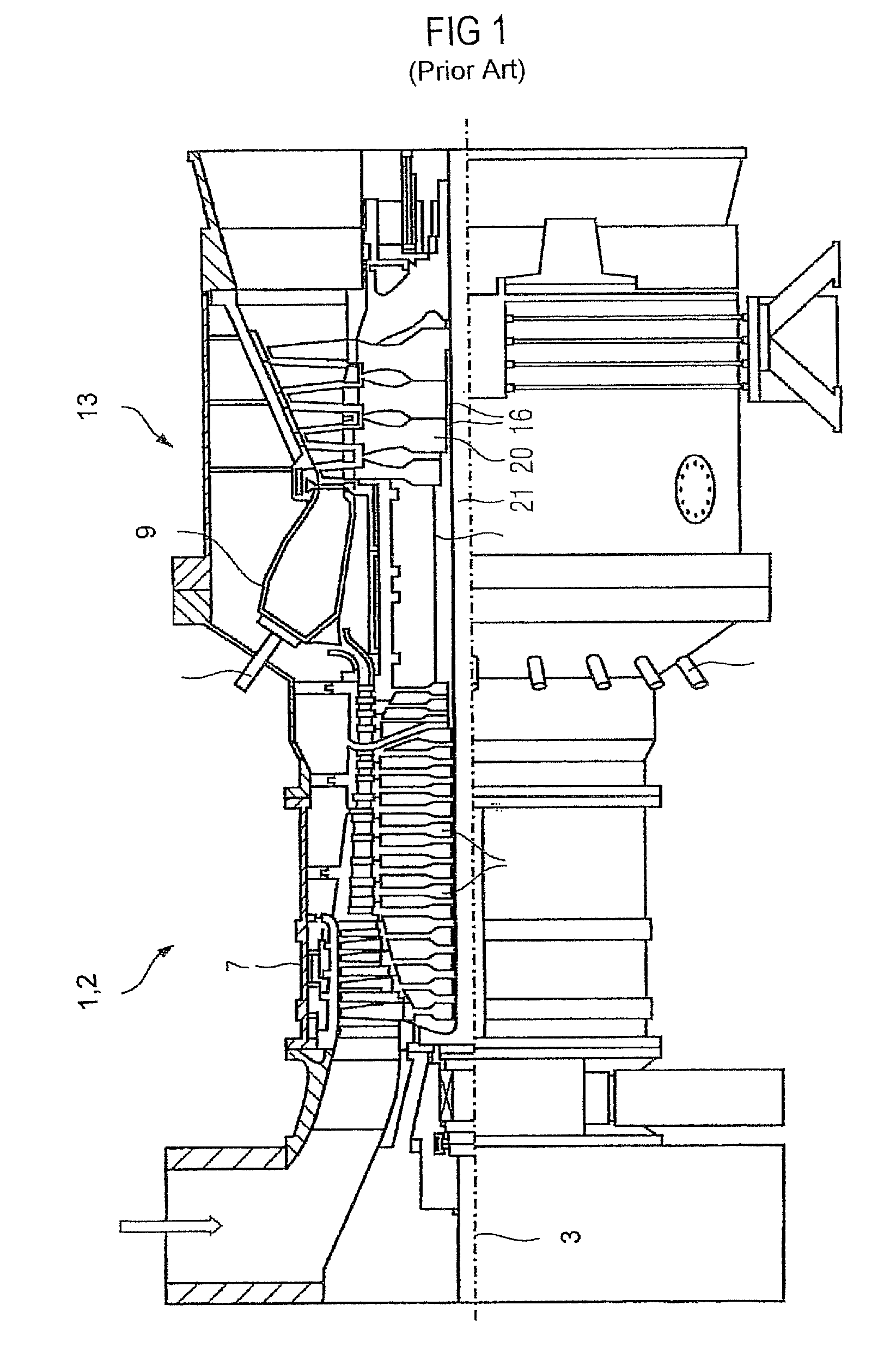
[0030]Gas turbines and their modes of operation are generally known. In this respect, FIG. 1 shows a turbo machine which is designed as a gas turbine 1 and has a rotor 5 which is mounted such that it can rotate about an axis of rotation 3. In the longitudinal extent of the rotor 5, a compressor 7 is followed by a combustion chamber 9 with burners 11. The turbine unit 13 is connected downstream of the combustion chamber 9. Both in the compressor 7 and in the turbine unit 13, the rotor 5 has a plurality of rotor disks 20 which bear against one another and in each of which there is a central bore 16, through which a tie rod 21 extends.

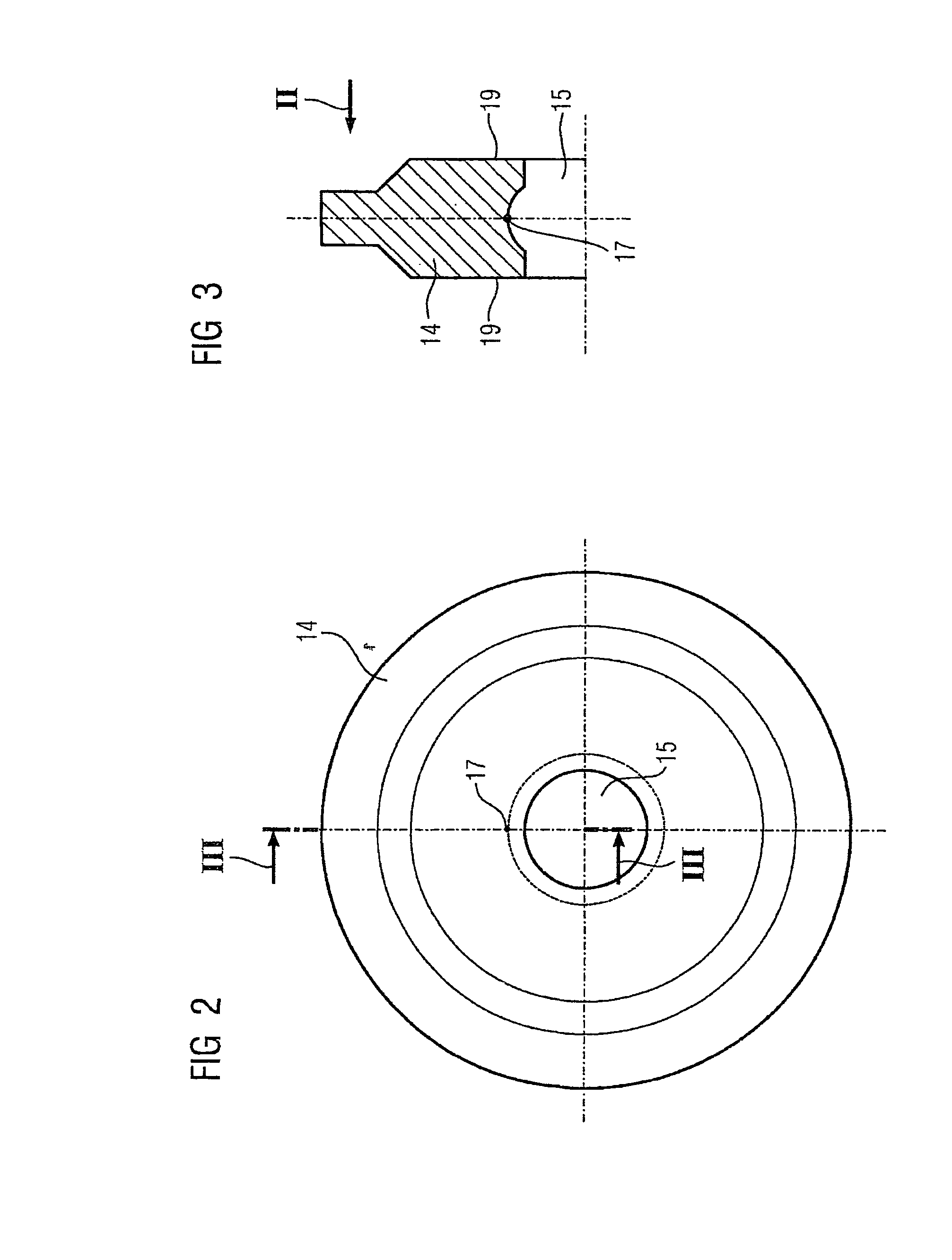
[0031]FIG. 2 shows the side view of a rotor disk 14 according to the invention, with a centrally arranged bore 15 which is partially convex in the axial direction, i.e. curves outwards in this direction.

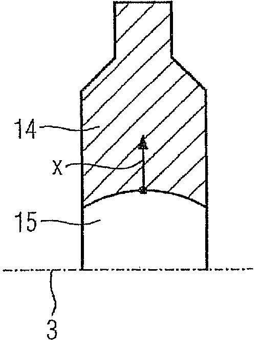
[0032]FIG. 3 shows a section through the rotor disk 14 according to the invention as shown in FIG. 2. The bore 15 is initially cylindrical in the axial di...


PUM

PropertyMeasurementUnit
Diameteraaaaaaaaaa
Lengthaaaaaaaaaa
Speedaaaaaaaaaa

Abstract

The invention relates to a rotor disk for the rotor of a non-positive displacement machine with at least one borehole extending in an axial direction. The aim of the invention is to provide a rotor disk for a non-positive displacement machine that has an increased serviceable life. To this end, the boring extends in an at least partially convex manner whereby having an enlarged diameter in the middle area in order to increase internal compressive stress an to reduce tangential stresses.

Description

CROSS REFERENCE TO RELATED APPLICATIONS[0001]This application is the US National Stage of International Application No. PCT / EP2005 / 052698, filed Jun. 10, 2005 and claims the benefit thereof. The International Application claims the benefits of European Patent application No. 04015806.5 filed Jul. 5, 2004. All of the applications are incorporated by reference herein in their entirety.FIELD OF INVENTION[0002]The invention relates to a turbo machine having a rotor which is mounted such that it can rotate about an axis of rotation and has at least one rotor disk in which is arranged at least one axially extending bore. The invention also relates to a rotor for a turbo machine and to a rotor disk having at least one bore extending axially through the rotor disk.BACKGROUND OF THE INVENTION[0003]Stationary gas turbines and aircraft turbines having rotors composed of a plurality of rotor disks are generally known. One central tie rod or a plurality of eccentric tie rods clamp the rotor disk...

Claims


Application Information

Patent Timeline
IPC IPC(8): F01D5/06
CPCF01D5/02F01D5/06F05D2250/29F05D2250/291Y10T29/49316F05D2250/71F05D2250/712F05D2230/10F05D2250/711F05D2250/19
Inventor HOELL, HARALDSCHAAL, REIMARSETZ, WERNER
Owner SIEMENS AG
Why Eureka
Try Eureka