Balance body ultrasound system

a balance body and ultrasound technology, applied in tomography, applications, instruments, etc., can solve the problems of large size of modern ultrasonic diagnostic systems, complex instruments, and inability to meet the needs of patients, and achieve the effect of increasing the sophistication of the system

Inactive Publication Date: 2010-10-26
FUJIFILM SONOSITE
View PDF78 Cites 38 Cited by
  • Summary
  • Abstract
  • Description
  • Claims
  • Application Information

AI Technical Summary

Benefits of technology

[0010]In a second embodiment of the present invention, a medical ultrasound system comprising a balance body incorporating system electronics, a power supply and a user interface wherein said user interface comprises a D-controller and a touch screen and a transducer assembly attached to said balanced body via a cable. Control of the medical ultrasound device is achieved through selecting throu

Problems solved by technology

As is well known, modern ultrasonic diagnostic systems are large, complex instruments.
However, such instruments lacked many of the advanced features of today's premium ultrasound systems such as color Doppler imaging and three dimensional display capabilities.
As ultra

Method used


Image

  • Balance body ultrasound system
  • Balance body ultrasound system
  • Balance body ultrasound system

Examples


second embodiment

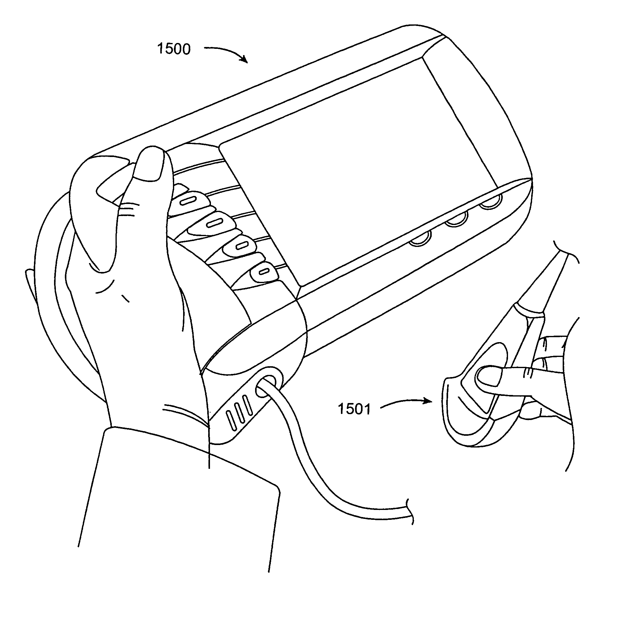
[0031]the present invention forms a lightweight ultrasound instrument comprising a body having a power supply, a user interface for controlling the instrument, a display screen, and a system electronics package capable of a plurality of diagnostic ultrasound modes. In this embodiment, the body may optionally be a balance body. A transducer assembly is attached to the body via a wire or thin flexible cable, the transducer assembly comprises a digital beam former, an A / D converter circuit and a transducer array. The body, transducer assembly and wire combined weigh less than three pounds.

[0032]The wire connecting the body and transducer assembly provides power to the transducer assembly, and a signal path for the body and transducer assembly to communicate using digital data. In this manner the need for an analog cable, having many data paths for analog signals, is eliminated, and spares additional weight. The signal from the transducer array returns through the digital beam former in...

third embodiment

[0034]In a third embodiment, a wireless diagnostic ultrasound system comprises a first body, and a second body. The first body is the main unit having system electronics, a user interface having a display screen and at least one control element, a first wireless transmit / receive circuit and a first power supply. The second body is a transducer assembly having a digital beam former, an A / D converter circuit, a transducer array, a second power supply and a second transmit / receive element such that the digital beam former of the second body can be controlled by the system electronics of the first body using the first and second transmit / receive circuits. The first and second transmit / receive circuits being a wireless means for communicating between the first body and the second body. Wireless data transfer and communication are well-understood technologies. Any standard wireless transmission standard capable of supporting the digital information communication of the present invention m...

fourth embodiment

[0036]In a fourth embodiment, the invention comprises a first body having system electronics (FIG. 20 at 2000), a first transmit and receive element (FIG. 20 at 2001), and a first power supply. The first body weighs less than two pounds. A second body houses the transducer assembly. The transducer assembly has a digital beam former, an A / D circuit, a transducer array, a second power supply, a second transmit and receive element and at least one control element. The second body weighs less than one pound. A head set (FIG. 20 at 2002) is provided comprising a visual display (FIG. 20 at 2003), a receive element and a third power supply such that the first body, second body and head set are all in real time communication with each other. U.S. Pat. No. 5,817,024 describes that video information can be communicated from a video output in several television formats. The user can control the system through the second body or first body while visualizing the ultrasound scan through the head ...


PUM


Abstract

The present invention relates to a hand held ultrasound system having a balance body, a transducer assembly connected to said balance body via a communication means and a plurality of control elements arranged in an ergonomic fashion on said balance body, such that a user may hold said system and operate at least one of said control elements with the same hand. In particular a medical ultrasound system comprising a balance body incorporating system electronics, a power supply and a user interface wherein the user interface comprises a D-controller and a touch screen and a transducer assembly attached to the balanced body by a cable. The present invention relates to a hand held ultrasound system having a balance body, a transducer assembly connected to said balance body via a communication means and a plurality of control elements arranged in an ergonomic fashion on said balance body, such that a user may hold said system and operate at least one of said control elements with the same hand. In particular a medical ultrasound system comprising a balance body incorporating system electronics, a power supply and a user interface wherein the user interface comprises a D-controller and a touch screen and a transducer assembly attached to the balanced body by a cable.

Description

CROSS-REFERENCES TO RELATED APPLICATIONS[0001]This application is a continuation-in-part of U.S. Ser. No. 10 / 062,179 filed Feb. 1, 2002 now U.S. Pat. No. 6,962,566; which was a continuation of U.S. Ser. No. 09 / 840,002, filed Apr. 19, 2001, now U.S. Pat. No. 6,569,101; and is also a continuation-in-part of U.S. Ser. No. 09 / 630,165, filed Aug. 1, 2000, now U.S. Pat. No. 6,416,475; which was a continuation-in-part of U.S. Ser. No. 09 / 167,964, filed Oct. 6, 1998 now U.S. Pat. No. 6,135,961; which was a continuation-in-part of U.S. Ser. No. 08 / 863,937, filed May 27, 1997, now U.S. Pat. No. 5,817,024; which was a continuation-in-part of U.S. Ser. No. 08 / 826,543, filed Apr. 3, 1997, now U.S. Pat. No. 5,893,363; which was a continuation-in-part of U.S. Ser. No. 08 / 672,782, filed Jun. 28, 1996, now U.S. Pat. No. 5,722,412, the full disclosures of which are incorporated herein by reference.BACKGROUND OF THE INVENTION[0002]1. Field of the Invention[0003]This invention relates to handheld ultra...

Claims


Application Information

Patent Timeline
IPC IPC(8): A61B8/00A61B5/0402A61B8/06A61B8/14G01S7/00G01S7/52G01S7/521G01S7/529G01S15/89G10K11/00G10K11/34
CPCA61B5/0402A61B8/56A61B8/06A61B8/13A61B8/14A61B8/4427A61B8/4455A61B8/462A61B8/467G01S7/003G01S7/5206G01S7/52079G01S7/5208G01S7/52084G01S7/529G01S15/899G10K11/004G10K11/345A61B8/54A61B8/00A61B8/4472A61B2560/0456G01S7/52034G01S7/52068G01S7/52071G01S15/8915A61B5/318
Inventor BARNES, STEPHANIE A.BUNCE, STEVEN MCABATIC, BRYAN S.LITTLE, BLAKE W.PURDUE, BILLSCHULTZ, JOHN D.RICE, KARI L.
Owner FUJIFILM SONOSITE
Why Eureka
Try Eureka