Parallel starting system having a low wiring expenditure

a starting system and parallel technology, applied in the direction of engine starting, machine/engine, electric generator control, etc., can solve the problems of high contact erosion and high risk of contact welding, and achieve the effect of improving switching reliability

Active Publication Date: 2010-10-26
SEG AUTOMOTIVE GERMANY GMBH
View PDF21 Cites 5 Cited by
  • Summary
  • Abstract
  • Description
  • Claims
  • Application Information

AI Technical Summary

Benefits of technology

[0006]An object of the present invention is therefore to improve the switching reliability. A further object of the present invention is to develop a parallel starting system that can be wired using minimum complexity. This object is achieved according to the present invention.
[0007]An important idea of the present invention is to separate the customary concatenation of the functions “engage” and “switch primary current” of conventional engaging relays and instead provide two relays, one of which (engaging relay) performs the function “engage” and the other (power relay) exclusively performs the function “switch primary current.” The engaging relay and the power relay are preferably designed as a structural unit together with the associated starter motor. This makes it possible to devise a parallel starting system that may be wired in a simple and low-cost manner and in which the power relay need not be designed for excessively high loads.
[0010]According to a second embodiment (FIG. 4) of the present invention, the engaging relays of two starters are connected in parallel with respect to their control terminals. The load terminals of the engaging relays are preferably connected in series, the first load terminal preferably being connected to terminal 30. The load terminal of the last engaging relay is preferably interconnected with the control terminal (50k) of a power relay. The power relays are preferably connected in parallel. The advantage of the series connection of the load terminals is that the flow of current between two starters is substantially lower.
[0012]Preferably, a three-pole connection is provided between two starters connected in parallel. If the connecting cable of a starter has a plug connection, it is possible to connect a plurality of starters in a simple manner. When wiring the starters, it is only necessary to take note of the position of the starter in question in the chain of starters.

Problems solved by technology

It is a disadvantage in this case that both engaging relays 4a, 4b must switch and conduct the same current for both starter motors 2a, 2b.
Noise-contaminated actuating signals (signal bounce) can therefore result in high contact erosion and a high risk of contact welding exists.

Method used


Image

  • Parallel starting system having a low wiring expenditure
  • Parallel starting system having a low wiring expenditure
  • Parallel starting system having a low wiring expenditure

Examples


Embodiment Construction

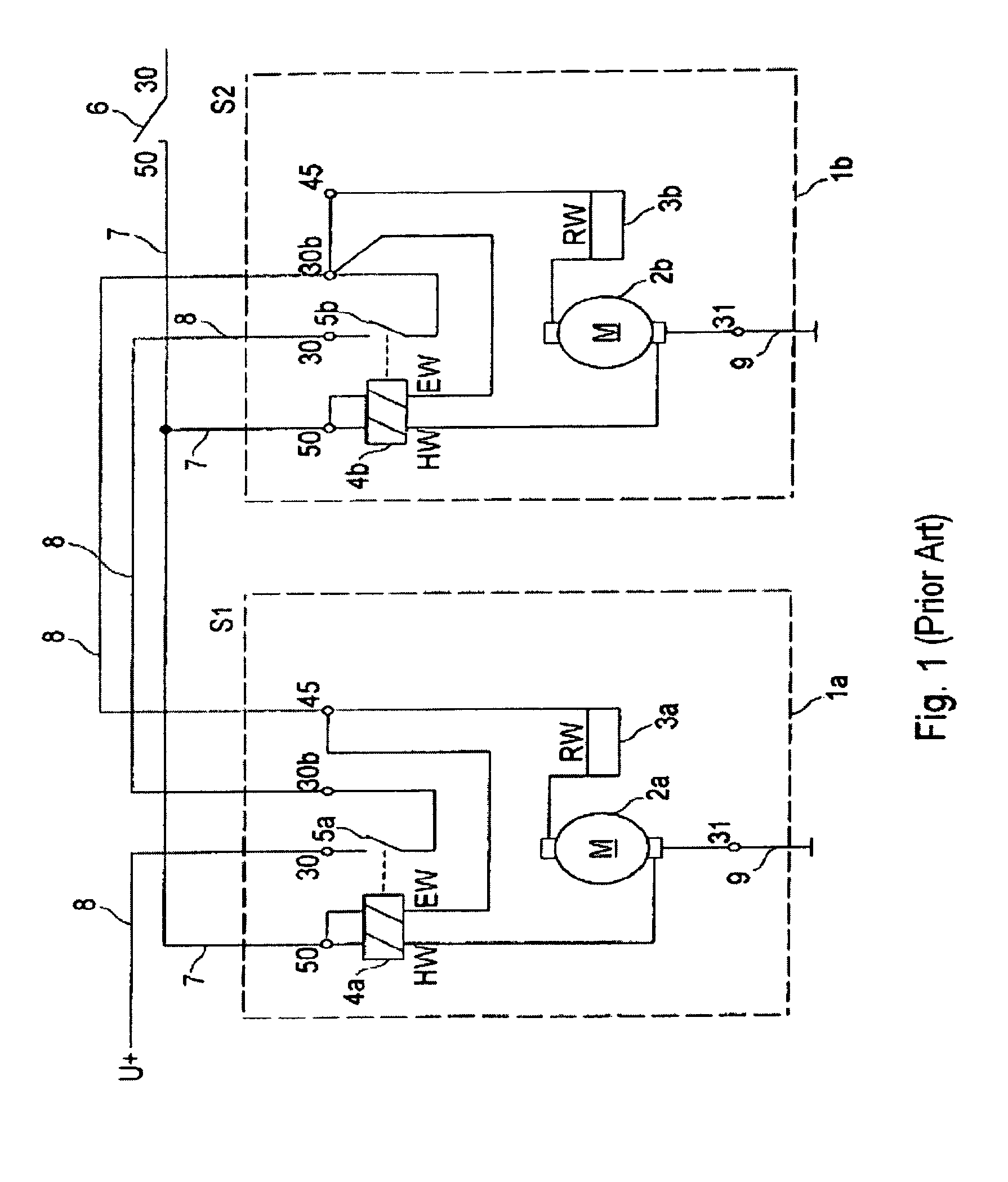
[0019]With respect to the explanation of FIG. 1, reference is made to the introduction of the background information.

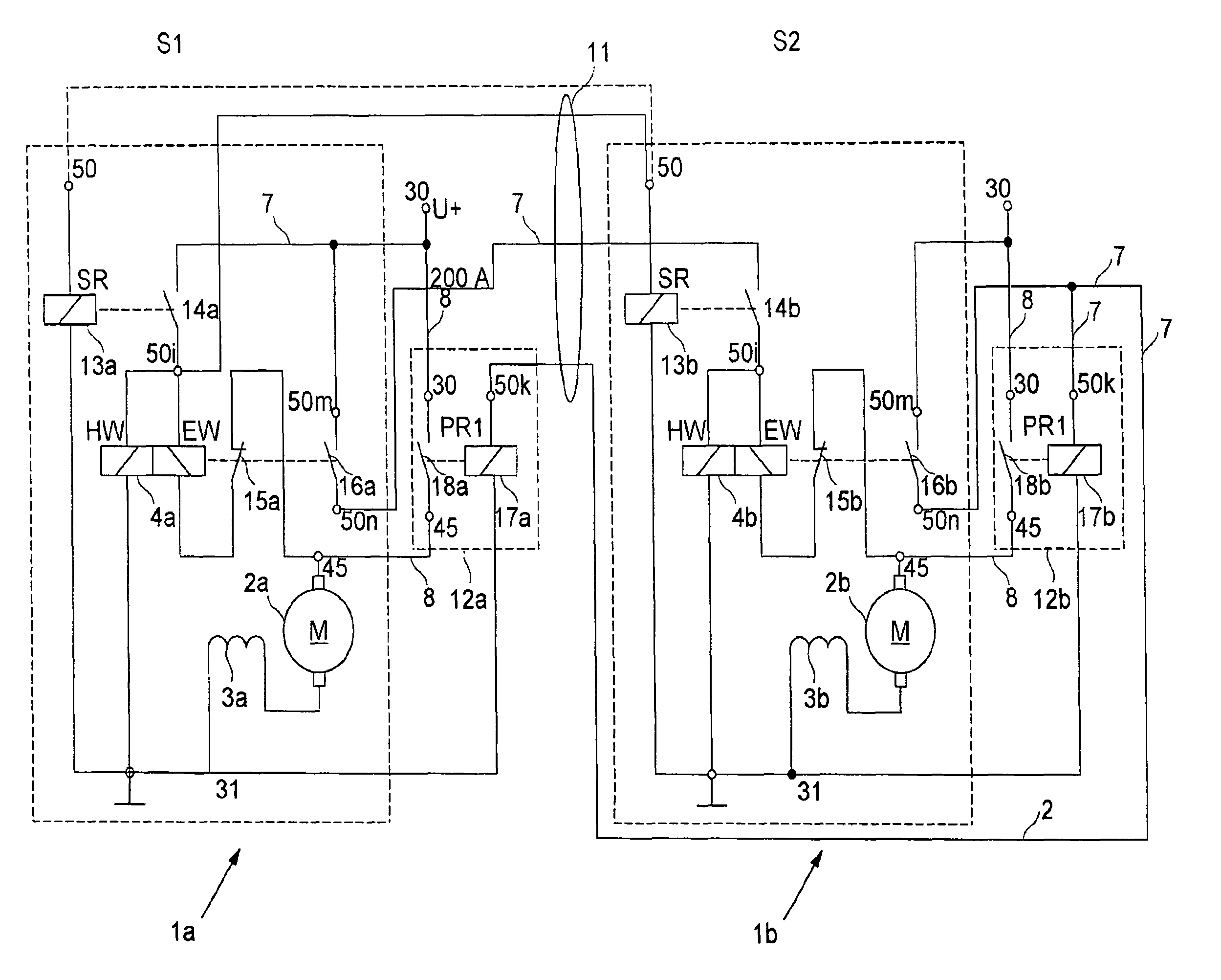
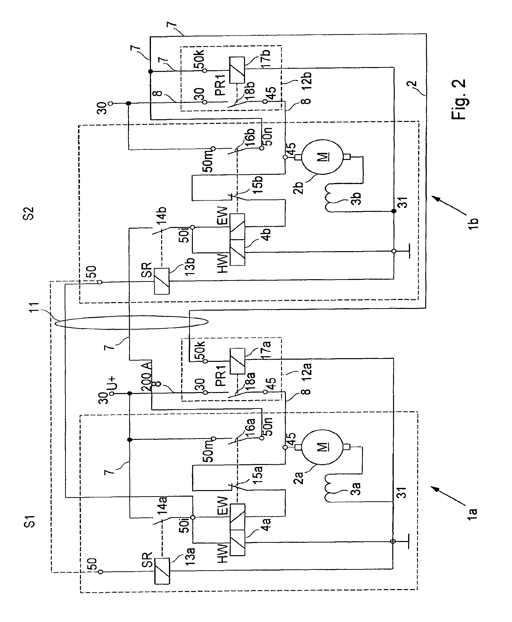
[0020]FIG. 2 shows a parallel starting system having two starters 1a, 1b. Each of starters 1a, 1b has a starting relay 13a, 13b, an engaging relay 4a, 4b, a power relay 12a, 12b and a starter motor 2a, 2b. The primary current of starter motors 2a, 2b is switched by power relays 12a, 12b. Engaging relays 4a, 4b are used only for engaging the pinion (not shown) with the ring gear and providing the starting current.

[0021]In a starting operation, starting relays 13a, 13b, which are connected in parallel and connected to terminal 50, pull in simultaneously and close associated switches 14a, 14b. This closes a current path 7 between terminal 30 and terminal 50i and current is supplied to the control terminal of both engaging relays 4a, 4b. In this case, engaging relays 4a, 4b are connected in series, i.e., the control terminal of engaging relay 4b is connected with the load...


PUM


Abstract

A starter system for starting internal combustion engines including a plurality of starters connected in parallel, each having a starter motor and an engaging relay. This parallel starting system may be implemented simply and cost-effectively if at least one of the starters includes a power relay which switches the primary current path to the associated starter motor, and the engaging relay, the power relay, and the starter motor are implemented as a structural unit.

Description

FIELD OF THE INVENTION[0001]The present invention relates to a parallel starting system for starting internal combustion engines.BACKGROUND INFORMATION[0002]Normally, electrically operated starters are used for starting internal combustion engines. In large engines having several tens or hundreds of liters of displacement such as, for example, marine engines, it is known to connect a plurality of starters in parallel to be able to provide the high starter power.[0003]FIG. 1 shows a parallel starting system from the related art having two starters 1a, 1b. Each of the starters includes a starter motor 2a, 2b and an engaging relay 4a, 4b which normally performs two functions. On the one hand, engaging relay 4a, 4b engages a pinion (not shown) driven by starter motor 2a, 2b with a ring gear of the internal combustion engine. On the other hand, engaging relay 4a, 4b closes a primary current path 8 via a normally open contact 5a, 5b when the pinion has engaged with the ring gear. This beg...

Claims


Application Information

Patent Timeline
Patent Type & Authority Patents(United States)
IPC IPC(8): F02N11/00
CPCF02N11/00F02N11/006F02N11/087F02N11/10F02N15/067F02N11/08
Inventor WANNER, HARTMUT
Owner SEG AUTOMOTIVE GERMANY GMBH
Why Eureka
Try Eureka