Fiber optic splice trays

a fiber optic splice and fiber optic technology, applied in the direction of cables, optical elements, instruments, etc., can solve the problems of optical fiber performance degradation and/or failure, and achieve the effects of improving functionality, improving slack storage, and small areas

Inactive Publication Date: 2010-10-26
CORNING OPTICAL COMM LLC
View PDF202 Cites 98 Cited by
  • Summary
  • Abstract
  • Description
  • Claims
  • Application Information

AI Technical Summary

Benefits of technology

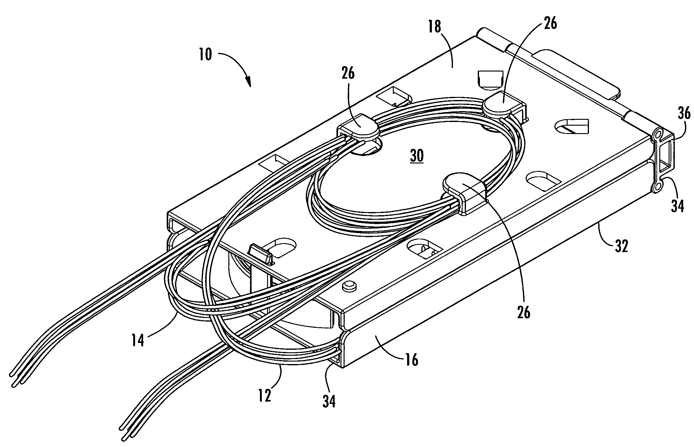
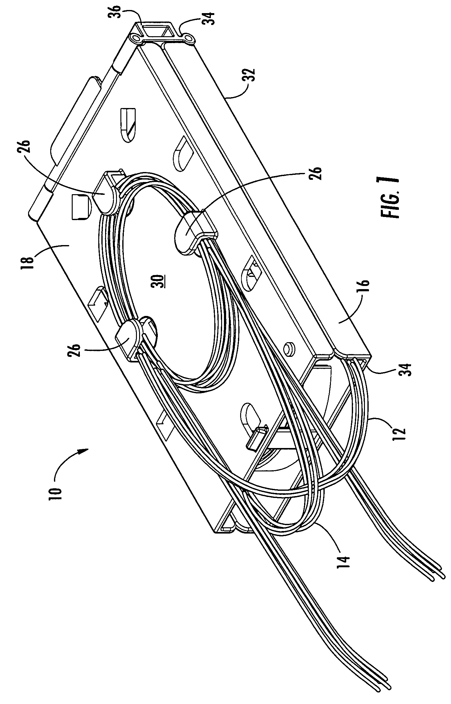
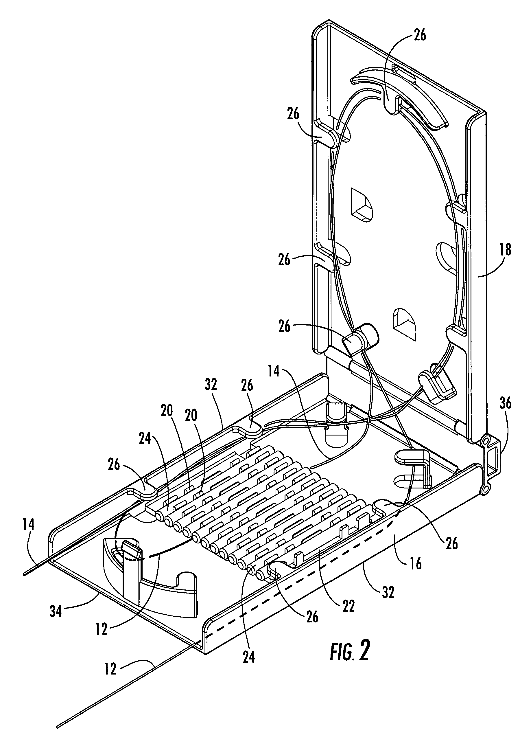
[0007]The various embodiments of the present invention address the above needs and achieve other advantages by providing splice trays that define generally smaller areas and / or volumes in addition to improved functionality, such as improved slack storage.
[0009]Another embodiment of the present invention includes a splice assembly adapted for use as a fiber drop terminal (“FDT”) within a multiple dwelling unit to optically connect one or more optical fibers of a distribution cable to one or more optical fibers of drop cables. The splice assembly comprises a base and a cover rotatably attached to the base. A splice tray is also included within the splice assembly and is attached to the base. A optical fiber routing device is provided with the splice tray and a cable routing device is provided on the base. The splice assembly is further adapted to be used with microstructured optical fibers that comprise a core region and a cladding region surrounding the core region, the cladding region comprising an annular hole-containing region comprised of non-periodically disposed holes. Therefore, the splice assembly provides convenient splicing and slack storage in a relatively small area and / or volume.
[0010]Additional embodiments of the present invention provide additional features to improve the size and / or functionality of the splice trays and / or splice assemblies.

Problems solved by technology

In order to splice and perform other related manipulation of the optical fibers, optical fiber slack is typically readily available, for example, to allow the fibers to be properly positioned for splicing and / or to position the splice in the splice holder without bending any portion of the optical fiber beyond the minimum bend radius of the optical fiber (which may result in performance degradation and / or failure of the optical fiber).

Method used


Image

  • Fiber optic splice trays
  • Fiber optic splice trays
  • Fiber optic splice trays

Examples


Embodiment Construction

[0028]The present invention now will be described more fully hereinafter with reference to the accompanying drawings, in which some, but not all embodiments of the invention are shown. Indeed, the invention may be embodied in many different forms and should not be construed as limited to the embodiments set forth herein; rather, these embodiments are provided so that this disclosure will satisfy applicable legal requirements. Although apparatus and methods for providing splices of microstructured optical fibers are described and shown in the accompanying drawings with regard to specific types of splice trays and splice assemblies, it is envisioned that the functionality of the various apparatus and methods may be applied to any now known or hereafter devised splice trays and splice assemblies in which it is desired to provide splices of optical fibers. Like numbers refer to like elements throughout.

[0029]With reference to FIGS. 1-16, a splice tray and a splice assembly in accordance...


PUM


Abstract

There is provided splice trays and splice assemblies that provide convenient access to optical fiber slack within a relatively small area or volume. Some splice trays are adapted for use with microstructured optical fibers to further reduce the size of the splice tray or splice assembly. Some splice trays provide fiber routing devices on the cover of the splice tray. The fiber routing device may be positioned on an inside surface of the cover and / or on an outside surface of the cover. The splice trays and / or splice assemblies may be used with or as fiber drop terminals used within multiple dwelling units.

Description

BACKGROUND OF THE INVENTION[0001]1. Field of the Invention[0002]The present invention is related to fiber optic splice trays, and more particularly, to fiber optic splice trays that provide novel sizes, shapes, and / or functionality.[0003]2. Description of Related Art[0004]Fiber optic data and communication systems employ splice trays and splice assemblies at various points along a distribution network. For example, a splice assembly may be used to connect drop cables to an express cable. The drop cables may lead to individual businesses or dwellings. The splice assembly often has a frame with an end cap on one or both ends to define a splice closure. The frame has provisions for receiving splice trays and storing slack fiber optic cable. The express cable typically has a jacket surrounding a number of buffer or express tubes. Each express tube typically has a plurality of optical fibers, usually from six to about twelve. The jacket of the cable will be stripped off and sealed around...

Claims


Application Information

Patent Timeline
Patent Type & Authority Patents(United States)
IPC IPC(8): G02B6/00
CPCG02B6/4454G02B6/3897
Inventor CASTONGUAY, GUYCLAPP, JR., DONNIE RAYFRAZIER, BRENT MICHAELPREVRATIL, KARYNE POISSANTRODRIGUEZ, DIANASIMS, STEVEN ROSSWORKS, ANTWAN JOCO'QUES
Owner CORNING OPTICAL COMM LLC
Why Eureka
Try Eureka