Transition balancing for noise reduction/Di/Dt reduction during design, synthesis, and physical design

a transition balance and noise reduction technology, applied in the field of noise reduction, can solve the problems of low-noise digital circuits, overall chip noise, highest supply and substrate noise, etc., and achieve the effect of reducing noise and reducing peak noise valu

Inactive Publication Date: 2010-10-26
GLOBALFOUNDRIES INC
View PDF19 Cites 8 Cited by
  • Summary
  • Abstract
  • Description
  • Claims
  • Application Information

AI Technical Summary

Benefits of technology

[0009]The embodiments disclosed herein describe a methodology for reducing noise associated with clocking of latches in pipelined designs. By dividing a chip into clocking domains, and clocking each domain with a same-frequency phase-shifted clock signal, the overall peak noise value associated with clocking of latches is averaged across the clock signal cycle, resulting in a significantly lower peak noise value. An interface between clocking domains synchronizes all clock signal domains allowing for a cycle time and latency equal to that of the conventional pipelined design. A synthesis methodology used to implement this variable-length pipeline is described. It is understood that the term clock can be used when referring to the clock signal herein described.

Problems solved by technology

Such integrated designs place noise-producing digital circuits next to noise-sensitive analog circuits and introduce new challenges of designing low-noise digital circuits and noise-immune analog circuits.
A large contributor to the overall chip noise is the clock signaling of latches, and the subsequent signal propagation in the logic that follows each latch.
The current demand from the supply spikes at the beginning of each clock signal cycle introducing the highest supply and substrate noise.
The noise problem is compounded by aggressively pipelined designs, which not only increase the signal frequency, but also the number of latches that need to be clocked.

Method used


Image

  • Transition balancing for noise reduction/Di/Dt reduction during design, synthesis, and physical design
  • Transition balancing for noise reduction/Di/Dt reduction during design, synthesis, and physical design
  • Transition balancing for noise reduction/Di/Dt reduction during design, synthesis, and physical design

Examples


Embodiment Construction

[0027]The embodiments of the invention and the various features and advantageous details thereof are explained more fully with reference to the non-limiting embodiments that are illustrated in the accompanying drawings and detailed in the following description. It should be noted that the features illustrated in the drawings are not necessarily drawn to scale. Descriptions of well-known components and processing techniques are omitted so as to not unnecessarily obscure the embodiments of the invention. The examples used herein are intended merely to facilitate an understanding of ways in which the embodiments of the invention may be practiced and to further enable those of skill in the art to practice the embodiments of the invention. Accordingly, the examples should not be construed as limiting the scope of the embodiments of the invention.

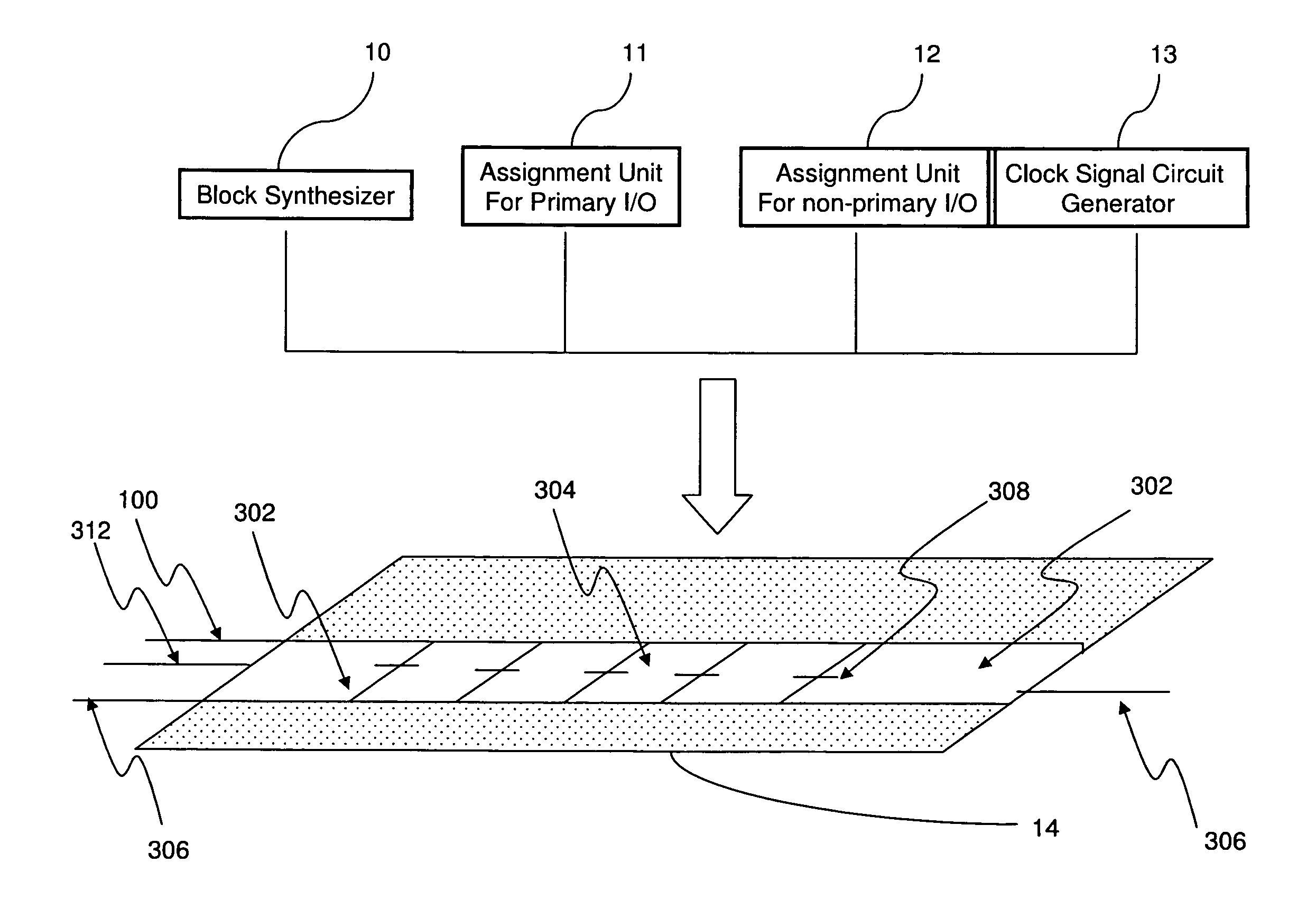
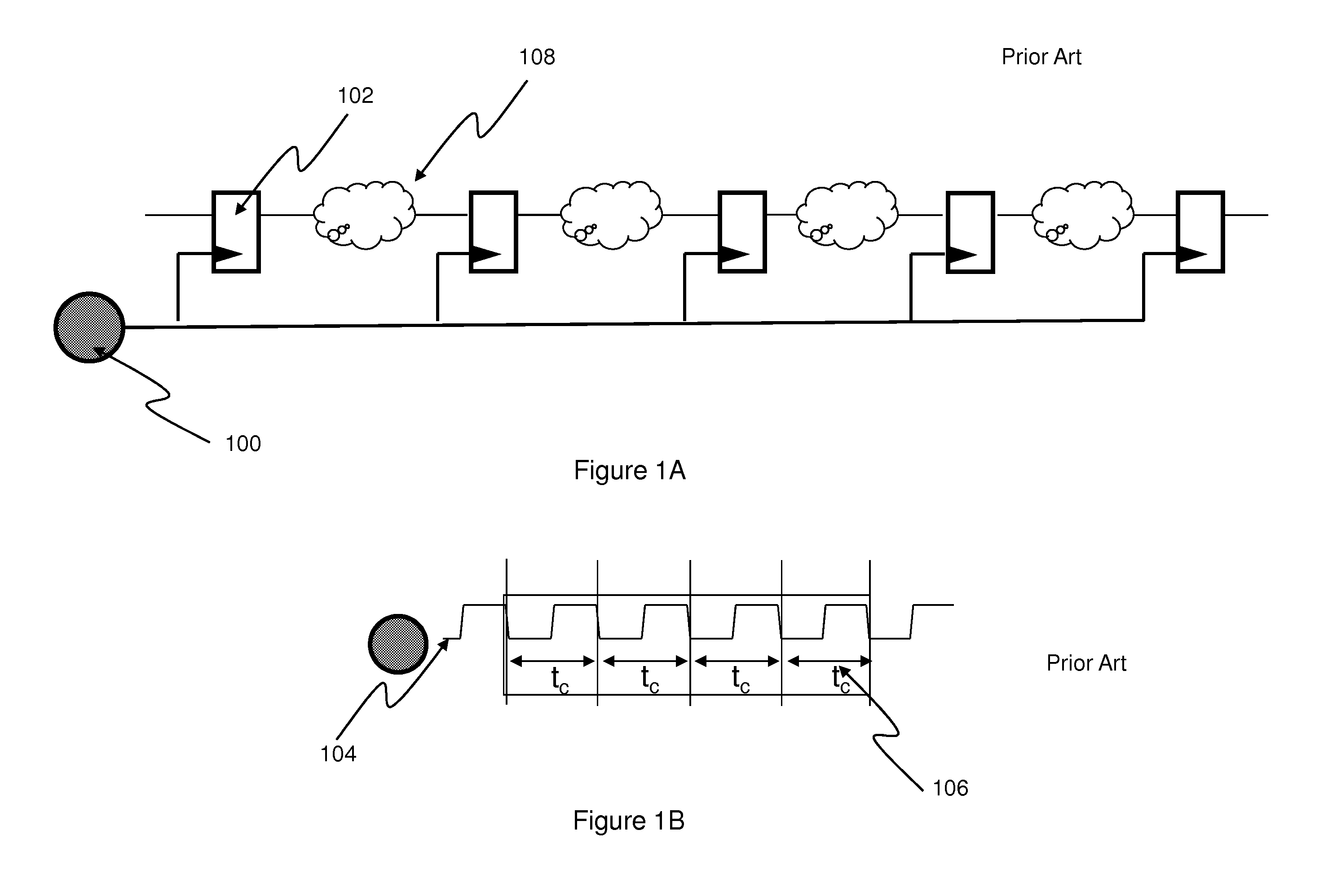
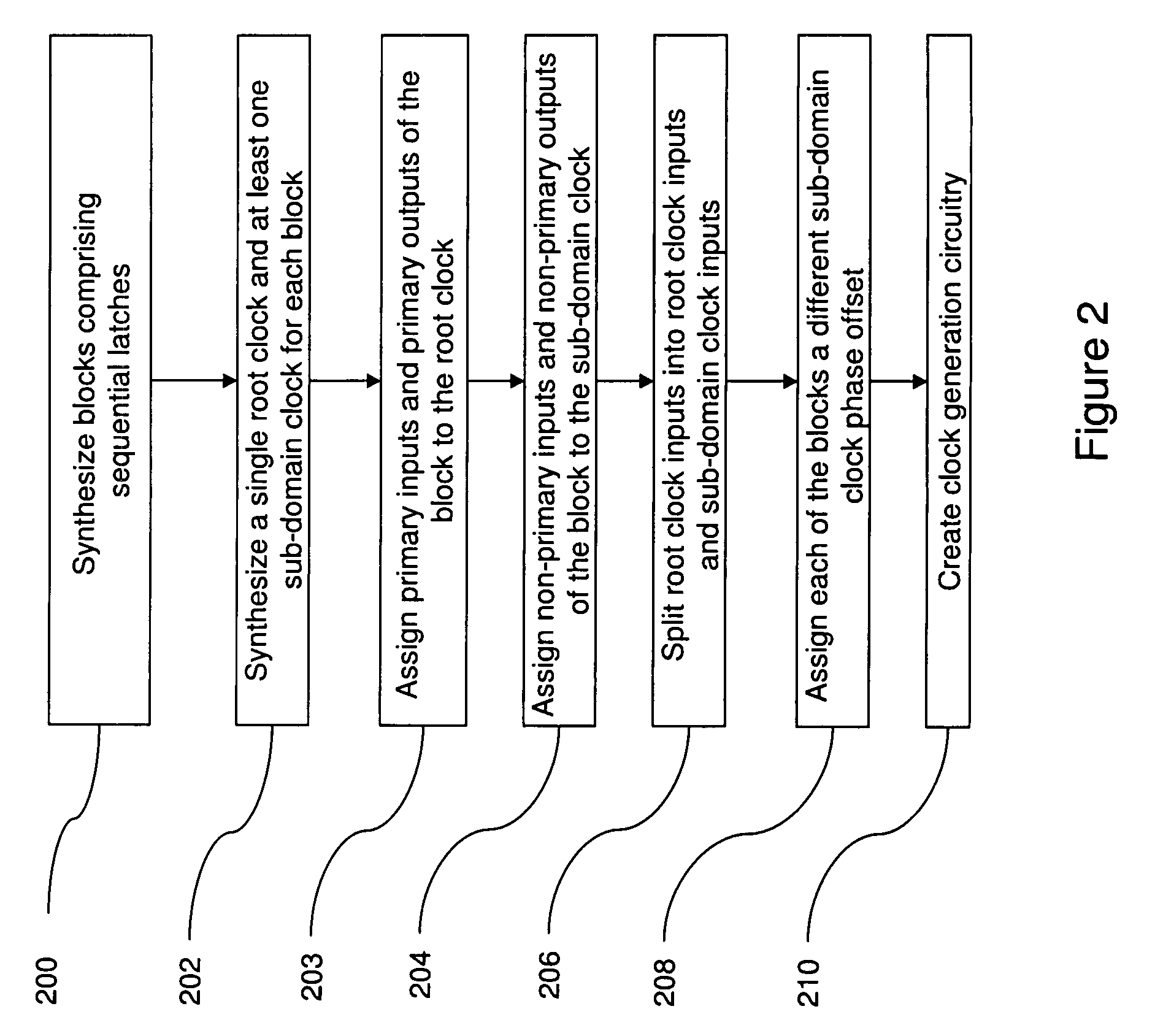
[0028]As mentioned, there remains a need for reducing noise in logic circuitry due to the clocking of latches in pipeline circuitry design. The ...


PUM


Abstract

An embodiment of a design structure is shown for noise reduction comprising synthesizing blocks of sequential latches, e.g., a pipeline circuit architecture or clocking domain, which comprises combinational logic, synthesizing a root or a master clock and at least one phase-shifted sub-domain clock for each block, assigning primary inputs and primary outputs of the block to the root clock, assigning non-primary inputs and non-primary outputs of the block to the sub-domain clock, splitting root clock inputs into root clock inputs and phase-shifted sub-domain clock inputs, assigning each of the blocks a different phase-shifted sub-domain clock phase offset, creating a clock generation circuitry for the root clocks and the phase-shifted sub-domain clocks.

Description

CROSS-REFERENCE TO RELATED APPLICATIONS[0001]This application is related to U.S. application Ser. No. 11 / 460,065 filed Jul. 26, 2006, the complete disclosure of which, in its entirety, is herein incorporated by reference.BACKGROUND[0002]1. Field of the Invention[0003]The embodiments of the invention generally relate to noise reduction, and, more particularly, to methods for synthesis of low-noise pipelined designs.[0004]2. Description of the Related Art[0005]Chips manufactured today are getting larger and continue to demand increased performance of the system. The increase in chip size is driven by the need to integrate an entire system-on-chip (SoC). SoC design minimizes chip-to-chip communication and thus generally improves overall performance. Such integrated designs place noise-producing digital circuits next to noise-sensitive analog circuits and introduce new challenges of designing low-noise digital circuits and noise-immune analog circuits.[0006]A large contributor to the ov...

Claims


Application Information

Patent Timeline
Patent Type & Authority Patents(United States)
IPC IPC(8): G06F17/50H04L7/00
CPCG06F17/505G06F17/5068G06F30/327G06F30/39G06F30/396
Inventor ARSOVSKI, IGORBUETI, SERAFINOIADANZA, JOSEPH A.NORMAN, JASON M.SHAH, HEMEN R.VENTRONE, SEBASTIAN T.
Owner GLOBALFOUNDRIES INC
Why Eureka
Try Eureka