Rotating bernoulli heat pump

a heat pump and rotating technology, applied in the field of bernoulli heat pumps, can solve the problem that heat pumps necessarily consume power

Inactive Publication Date: 2010-11-02
MACHFLOW ENERGY INC
View PDF34 Cites 3 Cited by
  • Summary
  • Abstract
  • Description
  • Claims
  • Application Information

AI Technical Summary

Problems solved by technology

Heat pumps necessarily consume power.

Method used


Image

  • Rotating bernoulli heat pump
  • Rotating bernoulli heat pump
  • Rotating bernoulli heat pump

Examples


Embodiment Construction

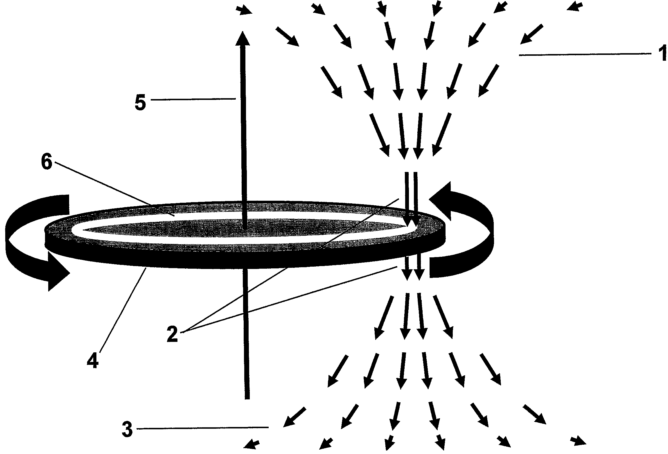
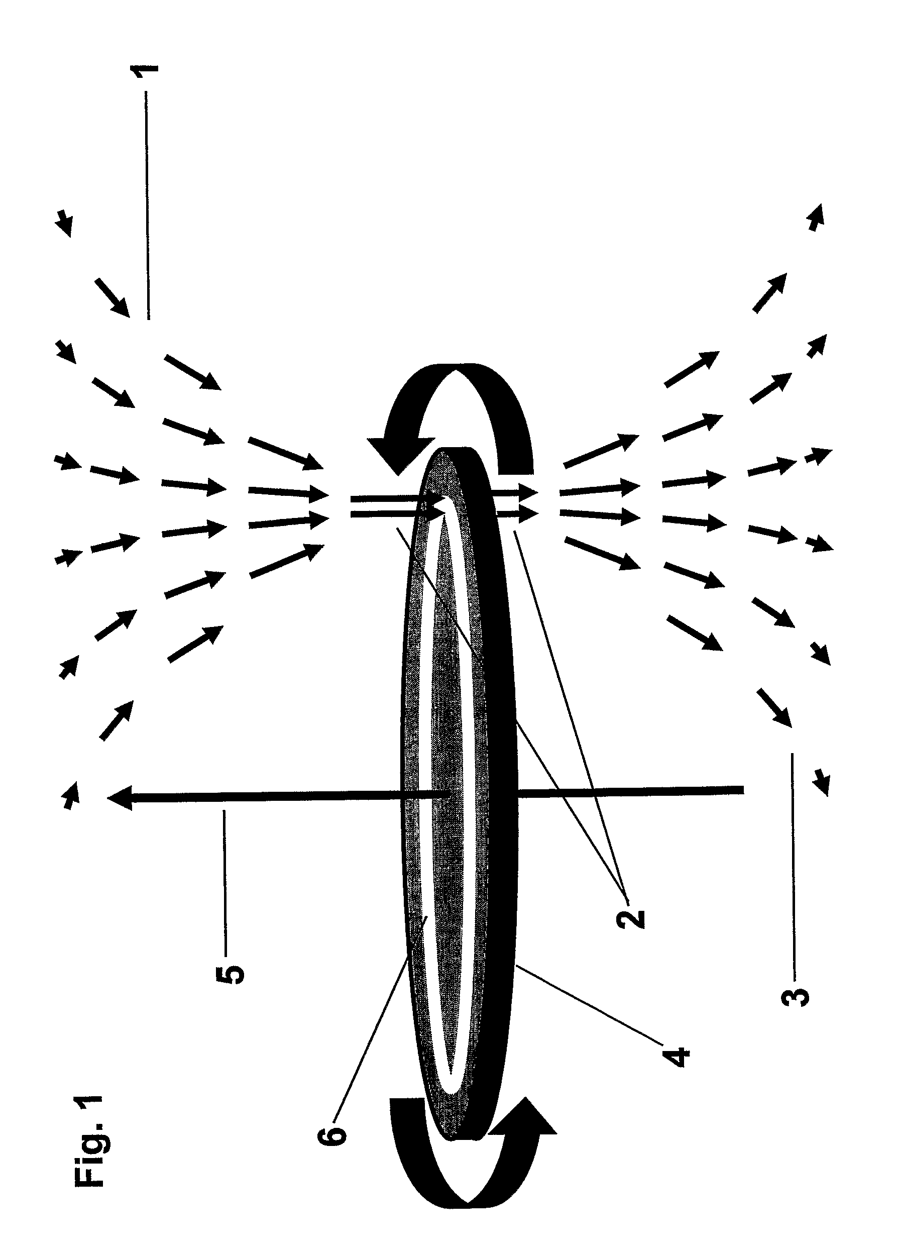
[0037]In embodiments of the invention, a rotating disk 4 creates a heat pump by maintaining within the heat-sink fluid flow an hour-glass-shaped Venturi 1-2-3, into which heat flows spontaneously as a result of the depressed temperature in the neck 2 of the Venturi. Heat flows within the disk 15, and enters the heat-sink Venturi at its low-temperature neck 2. Fluid flow in the neck 2 of the heat-sink Venturi is characterized by a direction. Three classes of embodiments are distinguished by this flow direction in the Venturi neck 2, relative to the rotation axis of the rotating disk. Flow in the Venturi neck 2 can be axial (FIGS. 1-6), radial (FIGS. 7 and 8) or circumferential (FIGS. 9 and 10), corresponding respectively to the three cylindrical coordinates, z, r and theta, appropriate to the description of rotating systems. In the figures describing fluid flows by fields of arrows, the length of the arrow represents the local speed of the flow in the direction of the arrow.

[0038]Con...


PUM


Abstract

Heat engines move heat from a source to a sink. In a subset of heat engines, called heat pumps, the temperature of the source is below that of the sink. A subset of heat pumps, called working-fluid heat pumps, accomplishes the heat-pumping function by varying the temperature of a working fluid over a range that includes the temperatures of both the source and the sink. A subset of working fluid heat pumps, called Bernoulli heat pumps, accomplish this temperature variation of the working fluid by means of Bernoulli conversion of random molecular motion into directed motion (flow). This invention is a Bernoulli heat pump in which Bernoulli conversion is accomplished using a rotating disk, similar to those used in computers for data storage. Most working fluid heat pumps used for cooling and heating accomplish the temperature variation by compression of the working fluid. In contrast to compression, Bernoulli conversion consumes no energy.

Description

CROSS REFERENCE TO RELATED APPLICATIONS[0001]This application claims priority to Provisional U.S. Patent application No. 60 / 580,790BACKGROUND OF THE INVENTION[0002]1. Field of the Invention[0003]The present invention relates to heat pumps, devices that move heat from a heat source to a warmer heat sink. More specifically, it relates to Bernoulli heat pumps.[0004]2. Discussion of Related Art[0005]Heat engines are devices that move heat from a heat source to a heat sink. Heat engines can be divided into two fundamental classes distinguished by the direction in which heat is moved. Heat spontaneously flows “downhill”, that is, to lower temperatures. As with the flow of water, such “downhill” heat flow can be harnessed to produce mechanical work, as illustrated by internal-combustion engines, e.g. Devices that move heat “uphill”, that is, toward higher temperatures, are called heat pumps. Heat pumps necessarily consume power. Refrigerators and air conditioners are examples of heat pumps...

Claims


Application Information

Patent Timeline
Patent Type & Authority Patents(United States)
IPC IPC(8): F25B27/00
CPCF25B9/00F25B23/00
Inventor WILLIAMS, ARTHUR R.
Owner MACHFLOW ENERGY INC
Why Eureka
Try Eureka