Countermass and countermass weapon

a counter-mass and weapon technology, applied in weapons, missile propulsion, firing/trigger mechanisms, etc., can solve the problem that the first container of non-rigid material is also rapidly destroyed, and achieve the effect of facilitating the enclosur

Active Publication Date: 2010-11-02
SAAB AB
View PDF11 Cites 4 Cited by
  • Summary
  • Abstract
  • Description
  • Claims
  • Application Information

AI Technical Summary

Benefits of technology

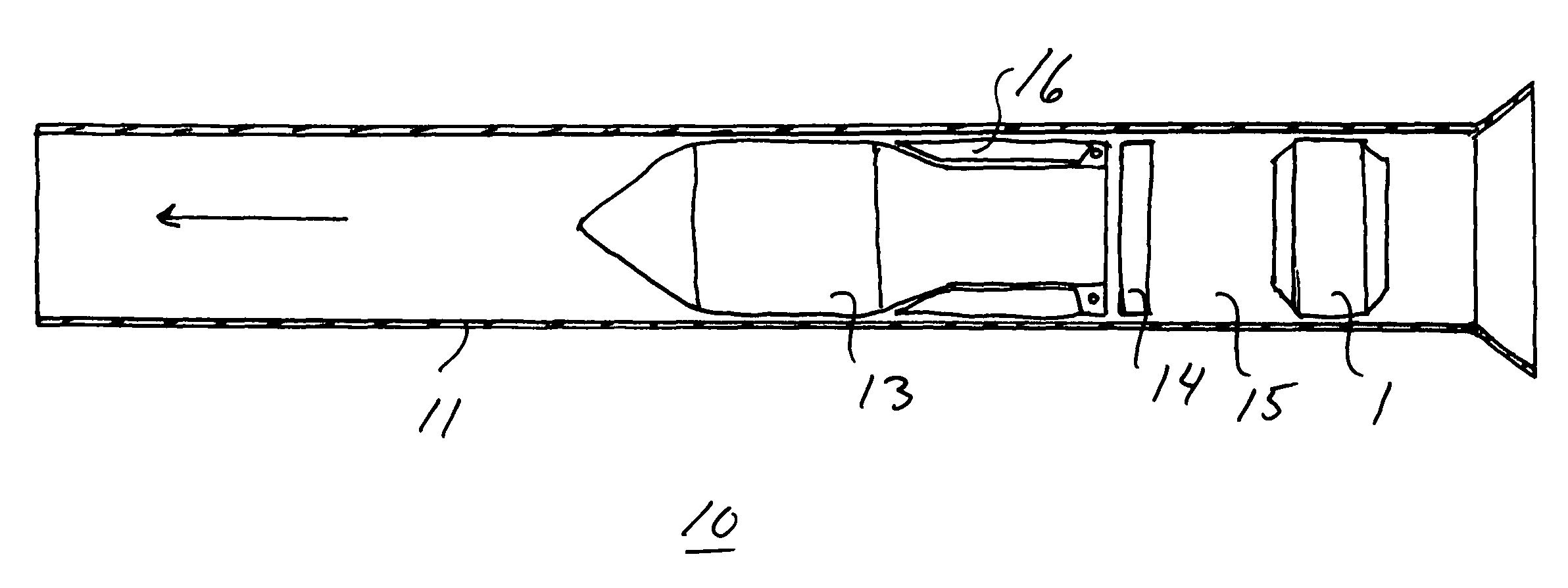
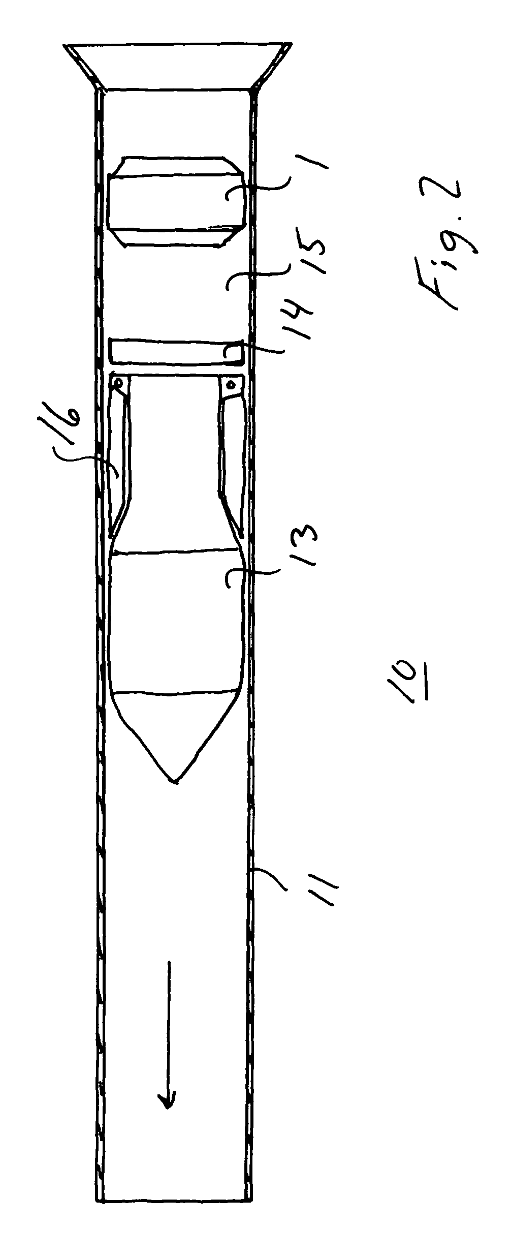
[0004]The object of the invention is to obtain a countermass and a countermass weapon that fulfils the requirements concerning back blast area and thus preventing generation of harmful high velocity fragments reaching an area to be safe a distance behind the weapon. A considered safety distance behind is often about 20 meters.
[0006]When firing such a weapon, the countermass behaves in a favourable way. The second container designed with damping characteristics is rapidly split into pieces and slowed down behind the weapon. The first container of non-rigid material is also rapidly destroyed. Accordingly there is no harmful ejection of material behind the weapon beyond a standard safety distance. The use of a first container of a non-rigid material also makes it possible to keep down costs for manufacturing the countermass and the time to produce different variants of countermass containers. It is easy to adapt the first container to different shapes of the inner walls of the outer second container. A new mould for the outer second container designed with damping characteristics can also be prepared within a short period. Furthermore the weight of the countermass containers is low so that the total weight of the weapon can be reduced.
[0007]According to a favourable development of the countermass the first container is made of a plastic foil. Another favourable development proposes that the first container is made of a metal foil, such as aluminium foil. The proposed foils are easy to adapt to almost any shape of the inner walls of the second container and are easily torn up behind the weapon avoiding harmful effects.
[0011]Preferably the second container consists of two essentially rotary symmetrical sections joint to each other after insertion of the first container. Such a designed second container facilitates the enclosure of the first container and also contributes to the sealing of the first container. Advantageously a peripheral part of the first container is clamped in between the sections of the second container.
[0012]According to one proposed embodiment the countermass of the weapon is fixed to the launcher tube by means of a clamping effect. According to another embodiment the countermass is fixed to the launcher tube by means of a screw joint. Both embodiments propose simple solutions how to arrange the countermass in the launcher tube.
[0013]In a particular embodiment the launchable unit is a rocket and in another embodiment the launchable unit is a projectile. The use of a countermass as claimed in these application fields enables a limitation of harmful fragments behind the weapon at the same time as the rocket or projectile is adequately launched from the launcher tube when firing.

Problems solved by technology

The first container of non-rigid material is also rapidly destroyed.

Method used


Image

  • Countermass and countermass weapon
  • Countermass and countermass weapon
  • Countermass and countermass weapon

Examples


Embodiment Construction

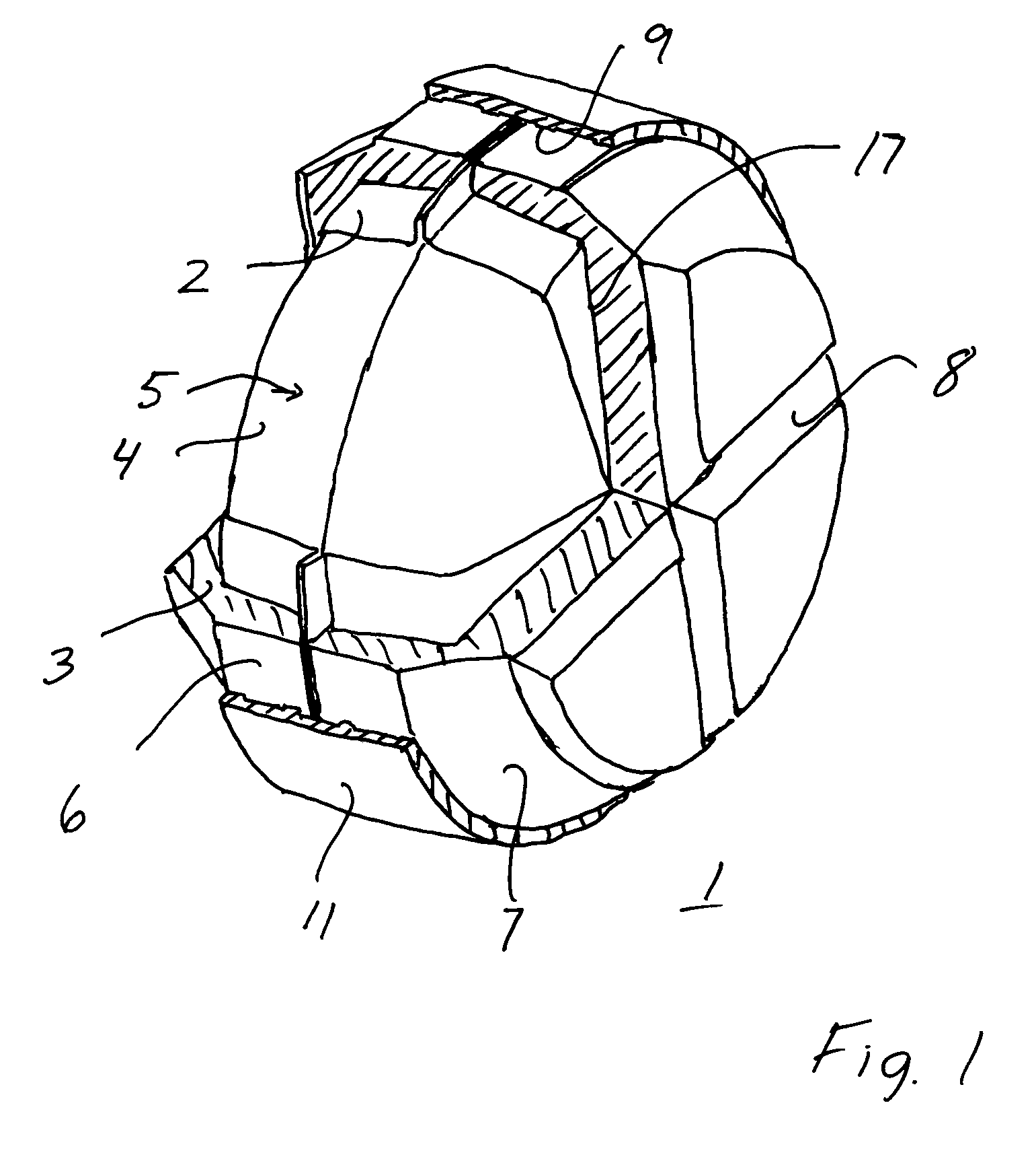
[0018]The countermass 1 shown in FIG. 1 comprises an inner container 2 and an outer container 3. Within the inner container 2 a liquid binder 4 is provided. This liquid binder binds a liquid 5.

[0019]The inner container 2 is made of a non-rigid material such as a plastic foil or metal foil. An example of a plastic foil that can be used is a foil of silicon. The proposed foils are very flexible and can easily be adapted to almost any desirable shape. In one embodiment the inner container 2 is designed as a sealable bag. The outer container 3 has damping characteristics and is suitably made of foam plastic, such as EPP (expanded polypropylene), Frigolit or other porous materials. In the proposed embodiment the outer container comprises two rotary symmetrical sections 6 and 7. The sections 6, 7 are provided with grooves 8 facilitating the split into pieces. Furthermore the periphery of the container sections 6 and 7 can be provided with recesses, not shown, intended for cooperation with...


PUM


Abstract

A countermass for use in a weapon to balance the forces arising when a launch able unit is launched from a launcher tube of the weapon. The countermass includes a first container enclosing a liquid. A countermass weapon includes a launcher tube open or openable in both ends. The launcher tube houses a launch able unit, a countermass including a first container enclosing a liquid, a pressure chamber, and a propellant charge that upon firing and combustion of the charge in cooperation with the pressure chamber and the countermass accelerates the launch able unit forwards in the tube at the same time as the countermass accelerates backwards in the tube. The first container is made of a non-rigid material. A second container is provided to cover or almost cover the first container. The second container is designed with damping characteristics.

Description

CROSS-REFERENCE TO RELATED APPLICATIONS[0001]This application claims priority under 35 USC §119 to European patent application No. 05445016.8 filed on 21 Feb. 2005.FIELD OF THE INVENTION[0002]The present invention relates to a countermass for use in a weapon to balance the forces arising when a launchable unit, such as a rocket, a projectile, a shell or the like, is launched from a launcher tube of the weapon, the countermass comprising a first container enclosing a liquid. The invention also refers to a countermass weapon comprising a launcher tube open or openable in both ends, the launcher tube housing a launchable unit such as a rocket, a projectile, a shell or the like, a countermass comprising a first container enclosing a liquid, a pressure chamber, and a propellant charge that upon firing and combustion of the charge in cooperation with the pressure chamber and the countermass accelerates the launchable unit forwards in the tube at the same time as the countermass accelerate...

Claims


Application Information

Patent Timeline
Patent Type & Authority Patents(United States)
IPC IPC(8): F41A1/08
CPCF41A1/10
Inventor OSTBERG, JONASJANSSON, .ANG.KE
Owner SAAB AB
Why Eureka
Try Eureka