
Surface tension seal

a surface tension and seal technology, applied in the direction of engine seals, leakage prevention, machines/engines, etc., can solve the problems of hydraulic actuators rare in micro system technology, tight tolerances, and large pressure drop of surface tension seals

Inactive Publication Date: 2010-11-02
K U LEUVEN RES & DEV
View PDF19 Cites 5 Cited by
  • Summary
  • Abstract
  • Description
  • Claims
  • Application Information

AI Technical Summary

Benefits of technology

"This patent describes a new seal technology for use in hydraulic, pneumatic, and hydro pneumatic devices. The seal is made of a fluid and can be used to seal gas or liquid in these devices. It is particularly useful for microdevices because it has low friction and low leakage. The seal is easy to manufacture and can be used in a variety of hydraulic and pneumatic actuators. The technology is based on a surface tension seal, which is similar to a rubber O-ring but made of fluid. The seal can be used as a dynamic seal or a static seal, and it can be designed to reduce leakage to zero. The technology is advantageous for microdevices because it is strong at microscale."

Problems solved by technology

Nevertheless, the surface tension seal can also create a considerable pressure drop.
However, omitting the pressure divider will always result in tighter tolerances when manufacturing the seal.
Despite these promising properties, hydraulic actuators are rare in Micro Systems Technology (MST) because of inherent sealing difficulties.
Most existing miniature hydraulic actuators suffer from either leakage or high friction.
These problems are due to the fact that the typically used rubber O-rings or lip seals are not appropriate for micro devices.
The main technological barrier for the development of such micro actuators is the lack of an appropriate sealing technology.

Method used


Image

  • Surface tension seal
  • Surface tension seal
  • Surface tension seal

Examples


example 1

Example of a Fabrication Process

[0116]Intended as exemplary only a cylinder and seal was fabricated as one monolithic structure. This minimizes the number of components thus simplifying the assembly of the actuator. The cylinder and the seal were made of brass. The fabrication of the actuator was divided in 8 steps as outlined in FIG. 14. In the first two steps, drilling and reaming with miniature tools defined the rough actuator shape. In step three the dimensions and the surface quality of the cylinder were improved by reaming. A tight tolerance on the seal diameter was achieved with planetary Micro Electro Discharge Machining (μEDM) in step 4. Electrode wear was compensated by Wire Electro-Discharge Grinding (WEDG) (Song X. et al. Proc. of SPIE Symposium on Micromachining and Microfabrication, Paris, 1999, 792-799). Next, a WEDG formed electrode was used to make the seal cavity. In step 6, a connection channel was drilled using μEDM. Finally, a Ga supply channel was glued with lo...


PUM


Abstract

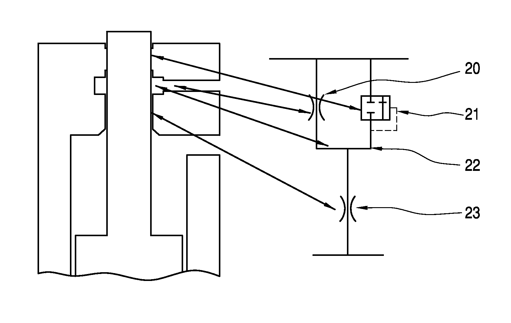
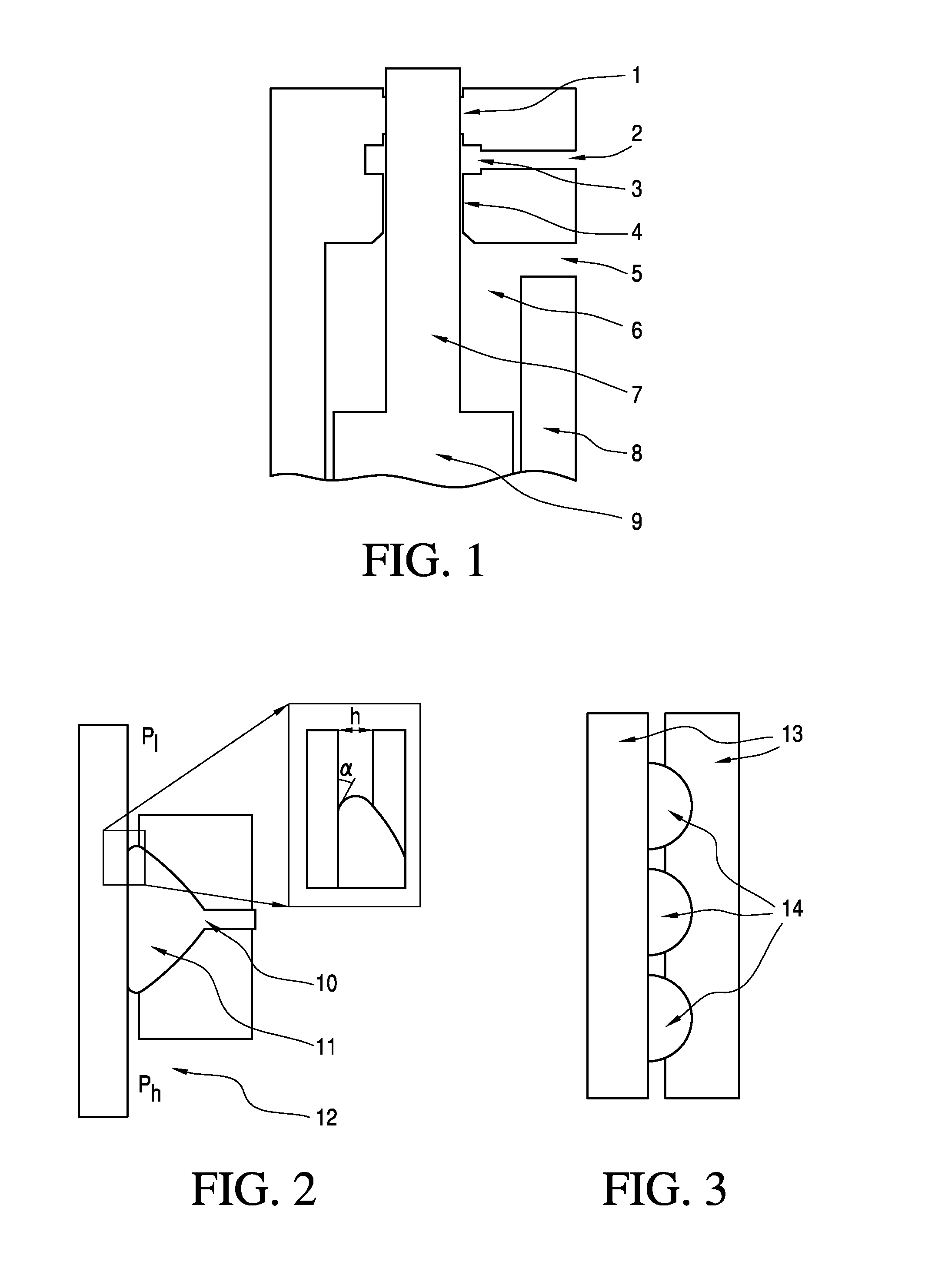
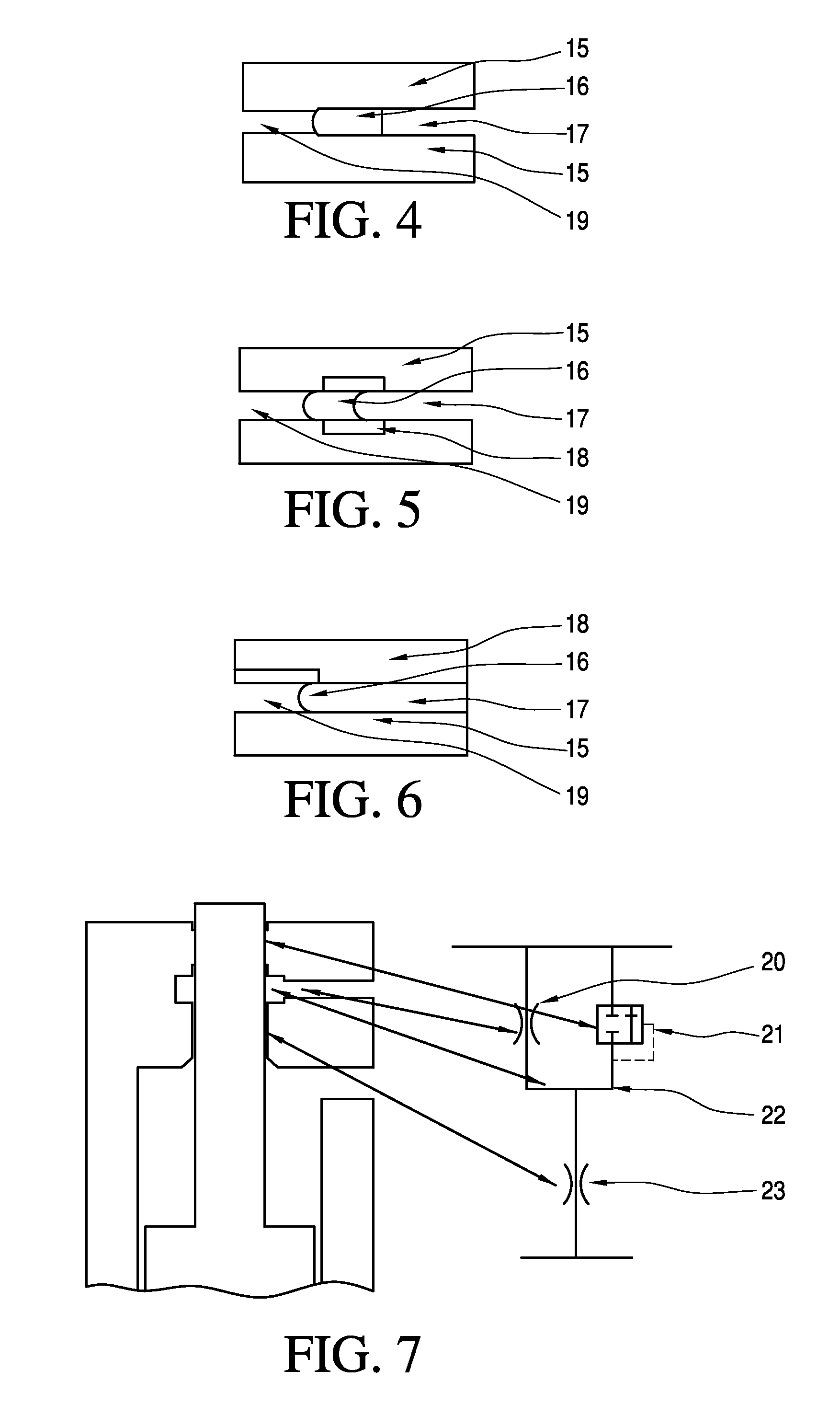
Present invention involves a seal means suitable to replace the classic seals. For instance the seal means of present invention can be a liquid seal ring (7) to replace the classic rubber seal rings. Such is liquid O-ring can be adapted to resists the actuation pressure relying on surface tension forces. Such liquid O-rings can also be linked in series, hereby increasing the maximum seal pressure. In a preferred embodiment the seal means of present invention comprises two major components, a surface tension seal (7) and a pressure divider (4). The pressure divider will comprise a system that generates a pressure drop. Such pressure divider can be located before the surface tension seal and perform the first pressure drop. The combination of these two systems has the advantage that the surface tension seal is able to reduce the leakage to zero or essentially zero and that the pressure divider is able to perform a large pressure drop. Nevertheless, the surface tension seal can also create a considerable pressure drop. This means that in applications where the seal pressure of the surface tension seal is not exceeded, the pressure divider can be omitted. However, omitting the pressure divider will always result in tighter tolerances when manufacturing the seal.

Description

TECHNICAL FIELD OF THE INVENTION[0001]This invention relates in general to a surface tension seal based on a fluid, which is particularly suitable to seal hydraulic, pneumatic or hydro pneumatic attenuators. The invention also relates to actuators, in particular microactuators, comprising at least one surface tension seal. The fluid seal can be used to seal a gas or a liquid. The surface tension seal can be used as a dynamic seal or as a static seal. A particular technical advantage is that this seal is characterised by low friction and / or low leakage. The invention is applicable for both macro and micro devices but is particularly interesting for the latter.BACKGROUND OF THE INVENTION[0002]This invention relates to a fluid seal, preferably a liquid seal, to seal a gas or a liquid in for instance hydraulic cylinders, pneumatic cylinders or hydropneumatic cylinders. In an embodiment of present invention a seal has been described which can be divided in two major components. The first...

Claims


Application Information

Patent Timeline
Patent Type & Authority Patents(United States)
IPC IPC(8): F16J15/40F15B15/14F16J15/43
CPCF15B15/1433F16J15/43
Inventor DE VOLDER, MICHAELREYNAERTS, DOMINIEK
Owner K U LEUVEN RES & DEV
Learn More