Paper conveying apparatus and method for flipping paper

a paper conveying and paper technology, applied in the direction of transportation and packaging, electrographic process, instruments, etc., can solve the problems of high production cost, complicated operation elements, and prone to paper jams, so as to reduce paper jams, reduce production costs, and simplify the structure

Inactive Publication Date: 2010-11-02
LITE ON TECH CORP
View PDF6 Cites 6 Cited by
  • Summary
  • Abstract
  • Description
  • Claims
  • Application Information

AI Technical Summary

Benefits of technology

[0006]In view of the aforesaid problems, the primary object of the invention is to provide a paper conveying apparatus that has a simpler structure and fewer elements, and includes a paper transmission mechanism that can reduce paper jams and is built in a smaller size.

Problems solved by technology

It needs complicated operation elements and is prone to generate paper jams.
U.S. Pat. No. 6,032,949 has an improved mechanism, but the production cost is higher.
While these techniques can flip paper for double-sided printing, they have common problems.
Namely, they adopt a complex design and mechanism, require many elements, maintenance is difficult, and the product is bulky.
Because of too many operation elements are involved, paper jams frequently occur.

Method used


Image

  • Paper conveying apparatus and method for flipping paper
  • Paper conveying apparatus and method for flipping paper
  • Paper conveying apparatus and method for flipping paper

Examples


Embodiment Construction

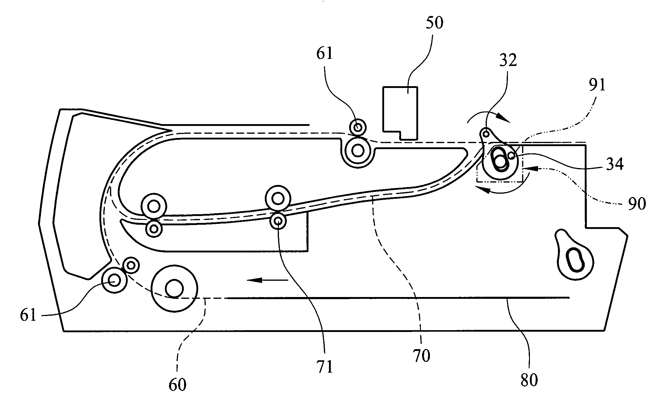
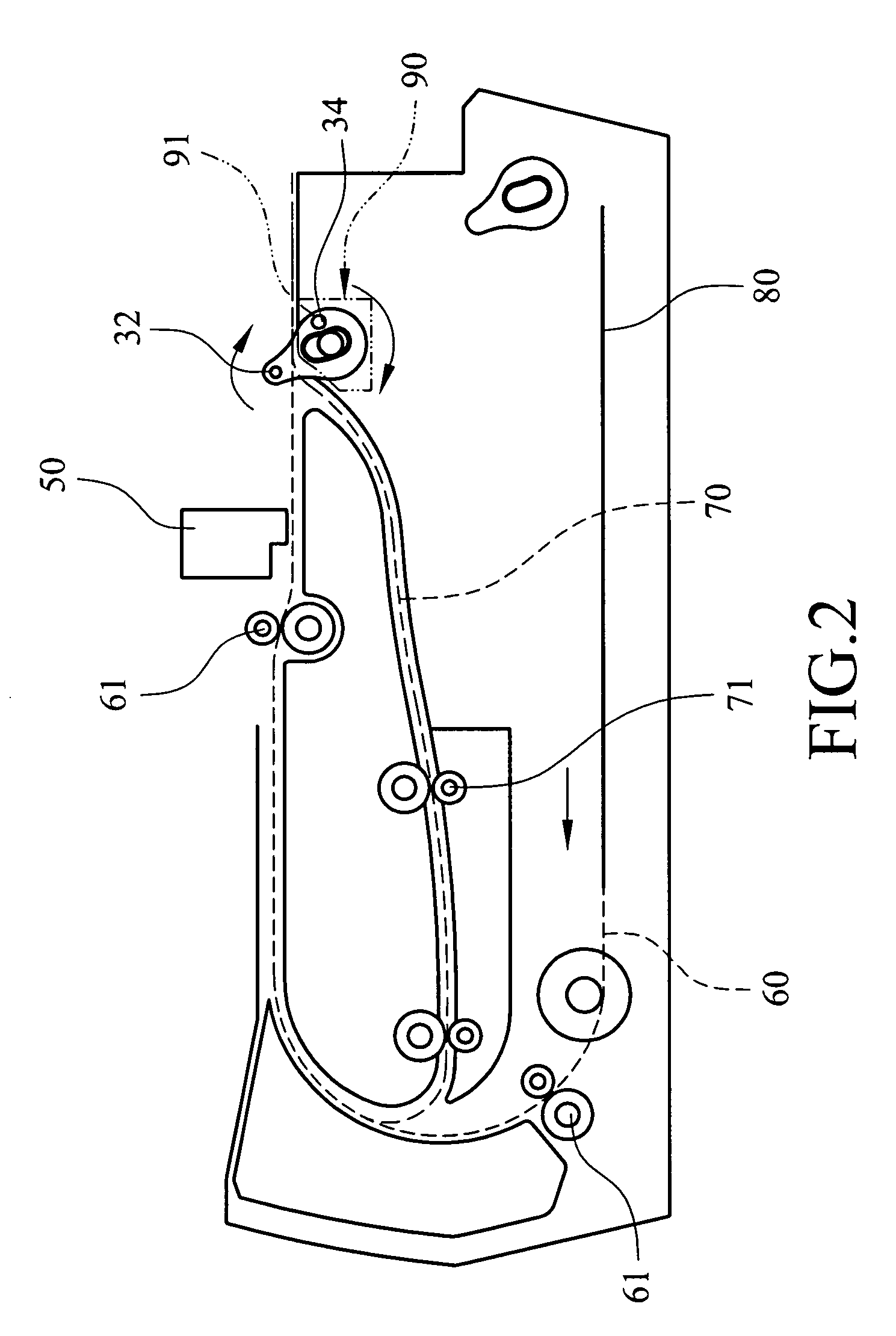
[0015]Refer to FIGS. 1 and 2 for an embodiment of the invention. The invention may be adopted for use on various scanning and printing devices such as scanners, facsimile machines, printers, copiers and MFPs to transport a sheet of paper 80. A printing device is used as an example in following discussion. The printing device has a first paper conveying path 60 for printing the first side of the paper and a second paper conveying path 70 connecting to the first paper conveying path 60. On the first paper conveying path 60 there is a plurality of first paper transporting rollers 61 and a bi-directional printing head 50. The second paper conveying path 70 also has a plurality of second paper transporting rollers 71. Depending on product types, the printing device may be replaced by a scanner to perform scanning operations for the paper 80.

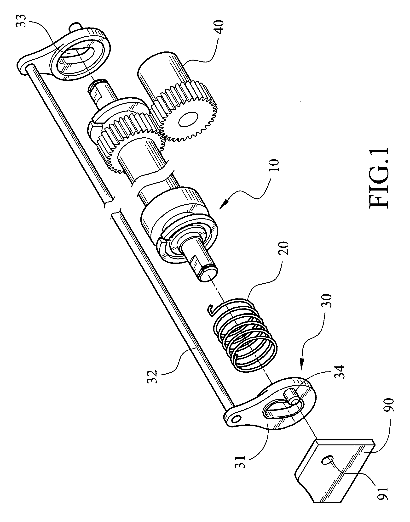
[0016]This embodiment further includes a paper feeding roller 10, a motion transfer member 20 and a paper depressing element 30 on the first paper co...


PUM


Abstract

A paper conveying apparatus and method for flipping paper includes a paper feeding roller that can rotate in a positive direction or in a reverse direction, a motion transfer member that has one end coupled with the paper feeding roller, and a paper depressing element coupled with another end of the motion transfer member to be driven and rotated. The method of flipping paper includes: first, feeding a sheet of paper into a first paper conveying path; next, depressing the paper into a second paper conveying path while the paper is leaving the first paper conveying path; and reentering the paper from the second paper conveying path into the first paper conveying path upside down.

Description

CROSS-REFERENCE TO RELATED APPLICATIONS[0001]This non-provisional application claims priority under 35 U.S.C. §119(a) on Patent Application No(s). 094107558 filed in Taiwan, R.O.C. on Mar. 11, 2005, the entire contents of which are hereby incorporated by reference.FIELD OF THE INVENTION[0002]The invention relates to a paper transporting mechanism for use on scanner and printer, and particularly to a paper conveying apparatus that has a duplex paper transporting function.BACKGROUND OF THE INVENTION[0003]Scanning and printing devices are widely used nowadays, especially in large enterprises and business organizations. They play important roles in making copies of documents for filing and in related printing and scanning operations.[0004]On scanning and printing devices such as facsimile machines, printers, scanners, or multi function printers (MFP), to process paper that has to be read, copied or printed on both sides, one approach is to flip the paper manually; another approach is to...

Claims


Application Information

Patent Timeline
Patent Type & Authority Patents(United States)
IPC IPC(8): B65H29/00
CPCB41J3/60B41J11/006B41J13/0045B41J13/14
Inventor SU, YU-JENCHIANG, SHU-YA
Owner LITE ON TECH CORP
Why Eureka
Try Eureka