Cooled component of a fluid-flow machine, method of casting a cooled component, and a gas turbine

a fluid-flow machine and fluid-flow technology, which is applied in the direction of marine propulsion, vessel construction, lighting and heating apparatus, etc., can solve the problems of slowing down the flow velocity of cooling fluid, and achieve the effect of reducing the flow velocity

Inactive Publication Date: 2010-11-02
SIEMENS AG
View PDF18 Cites 30 Cited by
  • Summary
  • Abstract
  • Description
  • Claims
  • Application Information

AI Technical Summary

Benefits of technology

[0008]The invention is based on the knowledge that, on account of the heat transfer, the cooling medium heats up steadily and expands at the same time during the flow in the cooling passage. However, this steady increase in volume continuously slows down the flow velocity of the cooling fluid, and downstream sections of the cooling passage therefore exhibit a changed heat transfer relative to upstream sections. In order to compensate for this effect, the cooling fluid is accelerated by imposing a swirl in order thus to compensate for the volume-related deceleration. A uniform heat transfer along the cooling passage can thus be set by imposing a sufficiently large swirl. An increase in the heat transfer is achieved by the swirl in the cooling fluid. Consequently, the component can be cooled more efficiently, a factor which may either be utilized for saving cooling fluid or for greater heat dissipation. In both cases, the cooling effect is increased, which leads either to an improved efficiency through an increased hot-gas temperature or to an improvement in economy due to reduced thermal loading of the component.
[0010]In an especially advantageous configuration of the invention, the cooling passage, like a multi-start screw, has a plurality of baffle elements with identical helix angles. This produces a core flow which flows in the center of the cooling passage and from which partial flows directed transversely to the main flow direction branch off continuously. Therefore all the flow-passage segments present between the baffle elements can communicate with one another. The formation of a controlled and effective core flow via the tips of the baffle elements in the longitudinal axis leads to increased performance values with regard to the heat transfer.
[0016]Adaptation to the local requirements or to the cooling can be achieved if the helix angle of the baffle elements varies along the cooling passage. A partial flow is thus more or less produced transversely to the main flow direction of the cooling fluid. Depending on the design, this permits acceleration or deceleration of the cooling fluid, so that the heat transfer from the outer wall into the cooling fluid can be advantageously influenced in this way.
[0020]The turbulators arranged in a turbine moving blade with a cooling passage are provided merely in that region or that part of the cooling-passage circumference which faces the suction-side outer wall. Due to the rotation of the rotor and of the turbine moving blade thus moving with it, secondary flows occur in the cooling fluid flowing in the cooling passage, and these secondary flows induce a varying passage-side heat transfer from the blade material into the cooling fluid along the circumference of the cooling passage. Due to the rotation, a higher streamline density (and thus a higher cooling-fluid pressure) prevails in that region of the circumference of the cooling passage which faces the pressure-side outer wall of the turbine moving blade than in that region which faces the suction-side outer wall, so that, on the passage side, the pressure-side outer wall is cooled more effectively compared with the suction-side outer wall. However, the suction-side outer wall of a turbine blade, on account of the flow of hot gas around it, is subjected to higher temperatures than the pressure-side outer wall. It is therefore desirable to cool the suction-side outer wall to a different degree compared with the pressure-side outer wall. This is taken into account by the turbulators being arranged merely in that region of the circumference of the passage which faces the suction-side outer wall. As a result, a greater passage-side heat transfer than hitherto can be achieved at this location.

Problems solved by technology

However, this steady increase in volume continuously slows down the flow velocity of the cooling fluid, and downstream sections of the cooling passage therefore exhibit a changed heat transfer relative to upstream sections.

Method used


Image

  • Cooled component of a fluid-flow machine, method of casting a cooled component, and a gas turbine
  • Cooled component of a fluid-flow machine, method of casting a cooled component, and a gas turbine
  • Cooled component of a fluid-flow machine, method of casting a cooled component, and a gas turbine

Examples


Embodiment Construction

[0030]Gas turbines and their modes of operation are generally known. FIG. 6 shows a gas turbine 11 with a compressor 13, a combustion chamber 15 and a turbine unit 17, which follow one another along a rotor 19 of the gas turbine 11. A driven machine, e.g. a generator (not shown), is coupled to the rotor 19 of the gas turbine 11.

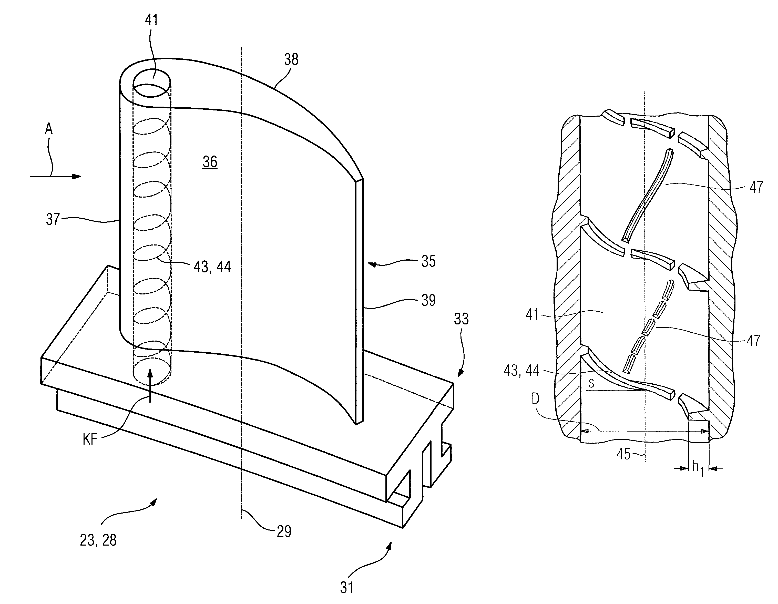
[0031]In both the compressor 13 and the turbine unit 17, guide blades 23 and moving blades 27 are provided in such a way as to follow one another in each case in blade rings 21, 25.

[0032]During operation of the gas turbine 11, air L is drawn in and compressed by the compressor 13. The compressed air is then fed to the combustion chamber 15 and is burned with the admixing of a fuel B to form a hot working medium A. The hot working medium A expands in the turbine unit 17 to perform work at the moving blades 27, which drive the rotor 19, and the latter drives the compressor and the driven machine (not shown).

[0033]In this case, the guide blades 23 and moving bla...


PUM


Abstract

A cooled component of a fluid-flow machine, through which a hot working medium flows, in particular a turbine blade of a gas turbine, in whose outer wall, to which the working medium can be applied, a cooling passage is provided, through which a cooling fluid can flow along its longitudinal axis.

Description

CROSS REFERENCE TO RELATED APPLICATIONS[0001]This application claims priority of European application No. 04017673.7 EP filed Jul. 26, 2004, which is incorporated by reference herein in its entirety.FIELD OF INVENTION[0002]The invention relates to a cooled component of a fluid-flow machine, through which a hot working medium flows, in particular a turbine blade of a gas turbine, in whose outer wall, to which the cooling medium can be applied, a cooling passage is provided, through which a cooling fluid can flow along its longitudinal axis. The invention also relates to a gas turbine having a cooled component and to a method of casting a cooled component.THE BACKGROUND OF INVENTION[0003]The journal “Konstruktion”, Zeitschrift für Produktentwicklung und Ingenieur-Werkstoffe [journal for product development and engineering materials], Volume 55, No. 9, page IW 9, discloses a heat exchanger tube which has ribs running along its longitudinal axis, lying on the inside and twisted about th...

Claims


Application Information

Patent Timeline
Patent Type & Authority Patents(United States)
IPC IPC(8): F01D5/18
CPCF01D5/187F01D11/24F01D25/12F23M5/085F23R3/005F05D2230/21F05D2250/25F05D2260/2212
Inventor DELLMANN, JURGENLANG, GERNOT
Owner SIEMENS AG
Why Eureka
Try Eureka