Modular connector system

a module connector and connector technology, applied in the direction of two-part coupling devices, connection contact material, coupling device connection, etc., can solve the problems of reducing the speed and operating efficiency of the connector, causing cross-talk, and causing electrical interference and cross-talk

Inactive Publication Date: 2010-11-02
TE CONNECTIVITY CORP
View PDF2 Cites 77 Cited by
  • Summary
  • Abstract
  • Description
  • Claims
  • Application Information

AI Technical Summary

Benefits of technology

[0005]In one embodiment, a connector assembly is provided. The connector assembly includes a contact module, signal contacts, and a ground contact. The contact module includes a dielectric body with mating and mounting edges and corresponding opposite back edges. The signal contacts are held within the contact module. The signal contacts include mating and mounting ends that protrude from the mating and mounting edges of the contact module, respectively. The signal contacts are arranged in a differential pair to convey differential signals. The ground contact is coupled to the contact module and includes mating and mounting ends that protrude from the mating and mounting edges of the contact module, respectively. The ground contact runs alongside the back edges of the contact module from the mounting edge to the mating edge.

Problems solved by technology

Electrical interference and cross talk may occur between the signal contacts of adjacent contact sets.
For example, two adjacent signal contacts may electrically interfere and produce cross-talk with each other.
The electrical interference and cross-talk among signal contacts may reduce the speed and operating efficiency of the connector.
The magnitude of cross-talk and interference may increase as the density of signal contacts in the connector is increased.
As a result, less room is provided for the ground contacts in the connectors and the magnitude of the cross-talk and interference may increase.
Manufacturing such modular connectors may be difficult and time consuming due to the increased density and / or decreased size of the modular connectors and the reduced area available for providing ground contacts in the connectors.
For example, the placement of ground contacts in relatively close proximity to signal contacts in a small connector may be difficult to accomplish.

Method used


Image

  • Modular connector system
  • Modular connector system
  • Modular connector system

Examples


Embodiment Construction

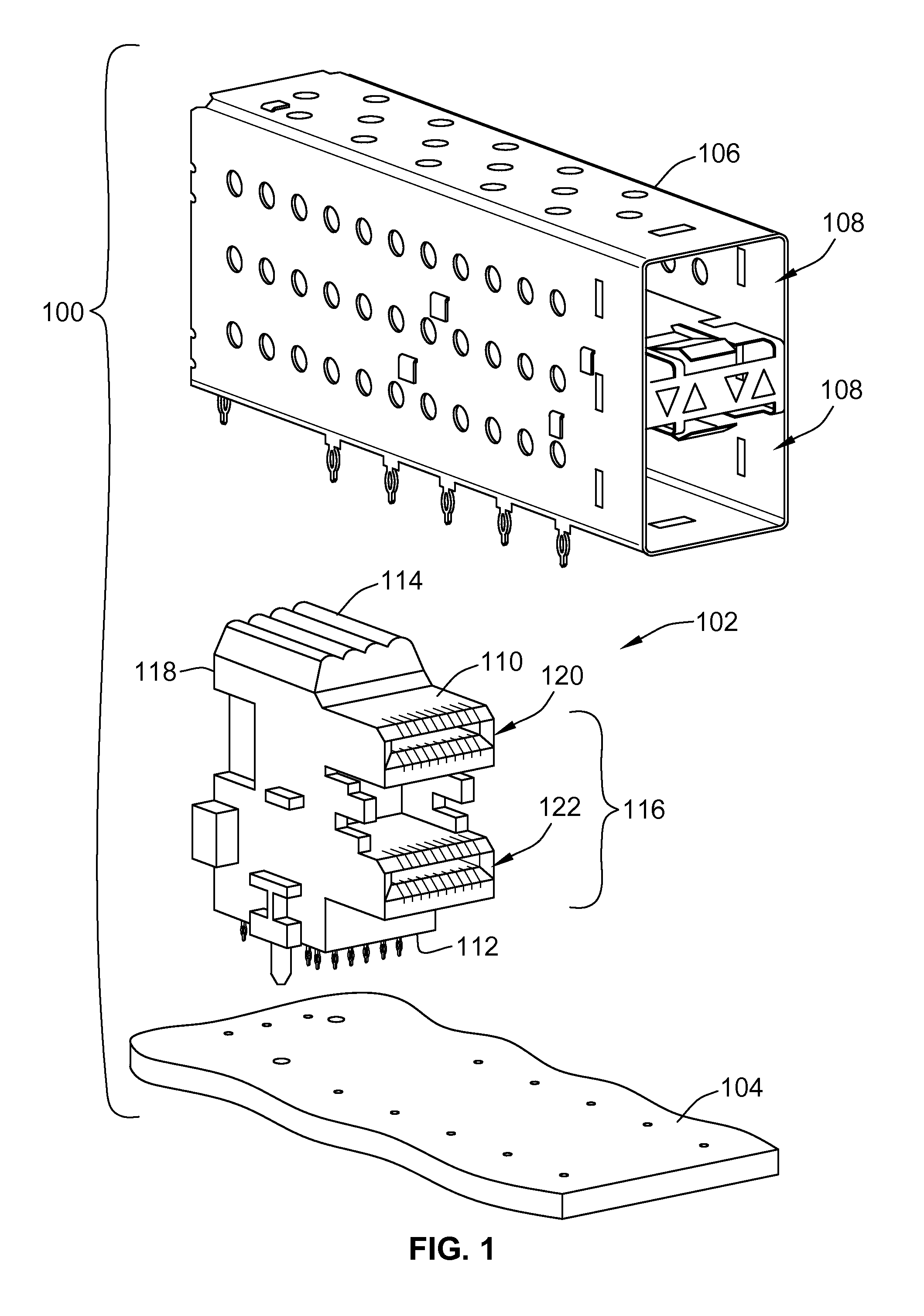
[0016]FIG. 1 is an exploded view of a modular connector system 100 in accordance with one embodiment of the present disclosure. The system 100 includes a connector assembly 102 mounted to a circuit board 104. The connector assembly 102 may be disposed within a connector cage 106 that also is mounted to the circuit board 104. The connector cage 106 may be mounted to the circuit board 104 to electrically couple the connector cage 106 with an electric ground reference of the circuit board 104. The connector cage 106 may shield the connector assembly 102 from electromagnetic interference. The connector cage 106 is a conductive body that includes several ports 108. The ports 108 receive mating connectors (not shown) that mate with the connector assembly 102 to communicate data and / or power therebetween. By way of non-limiting example only, the ports 108 may have dimensions that are sized to receive a small form-factor pluggable connector or transceiver that mates with the connector assem...


PUM


Abstract

A connector assembly includes a contact module, signal contacts, and a ground contact. The contact module includes a dielectric body with mating and mounting edges and corresponding opposite back edges. The signal contacts are held within the contact module. The signal contacts include mating and mounting ends that protrude from the mating and mounting edges of the contact module, respectively. The signal contacts are arranged in a differential pair to convey differential signals. The ground contact is coupled to the contact module and includes mating and mounting ends that protrude from the mating and mounting edges of the contact module, respectively. The ground contact runs alongside the back edges of the contact module from the mounting edge to the mating edge.

Description

BACKGROUND OF THE INVENTION[0001]One or more embodiments of the invention described herein generally relate to electrical connectors and, more particularly, to a connector system for communicating relatively high speed differential signals.[0002]Modular connectors are used in electronic systems, such as computer systems. The modular connectors may be used to connect various components within the systems, such as devices or networks, with the computers. Typically, the modular connectors represent either a plug assembly or a header assembly each of which is mated with another connector to provide an electrical connection between components of the system. The modular connectors typically include several signal contacts and ground contacts. The signal and ground contacts may be arranged in rows and / or columns. Some known connectors include signal contacts arranged in pairs that, along with a corresponding ground contact, form a contact set that transmits a differential signal. Electrica...

Claims


Application Information

Patent Timeline
Patent Type & Authority Patents(United States)
IPC IPC(8): H01R4/66
CPCH01R23/7073H01R13/6471H01R13/6586H01R9/2408H01R12/724
Inventor WESTMAN, JOHN EUGENEMCMASTER, JR., BRIAN KEITHFOGG, MICHAEL W.
Owner TE CONNECTIVITY CORP
Why Eureka
Try Eureka