
Semi-transparent TFT array substrate, and semi-transparent liquid crystal display with transparent pixel electrode and contrast reduction preventive electrode connected in the same layer

a liquid crystal display and preventive electrode technology, applied in semiconductor devices, optics, instruments, etc., can solve the problems of short circuit between the preventive electrode and the electrode surface, black dot defect generation of the pixel subjected to the short circuit, so as to avoid reflective contrast reduction

Inactive Publication Date: 2010-11-02
MITSUBISHI ELECTRIC CORP
View PDF11 Cites 2 Cited by
  • Summary
  • Abstract
  • Description
  • Claims
  • Application Information

AI Technical Summary

Benefits of technology

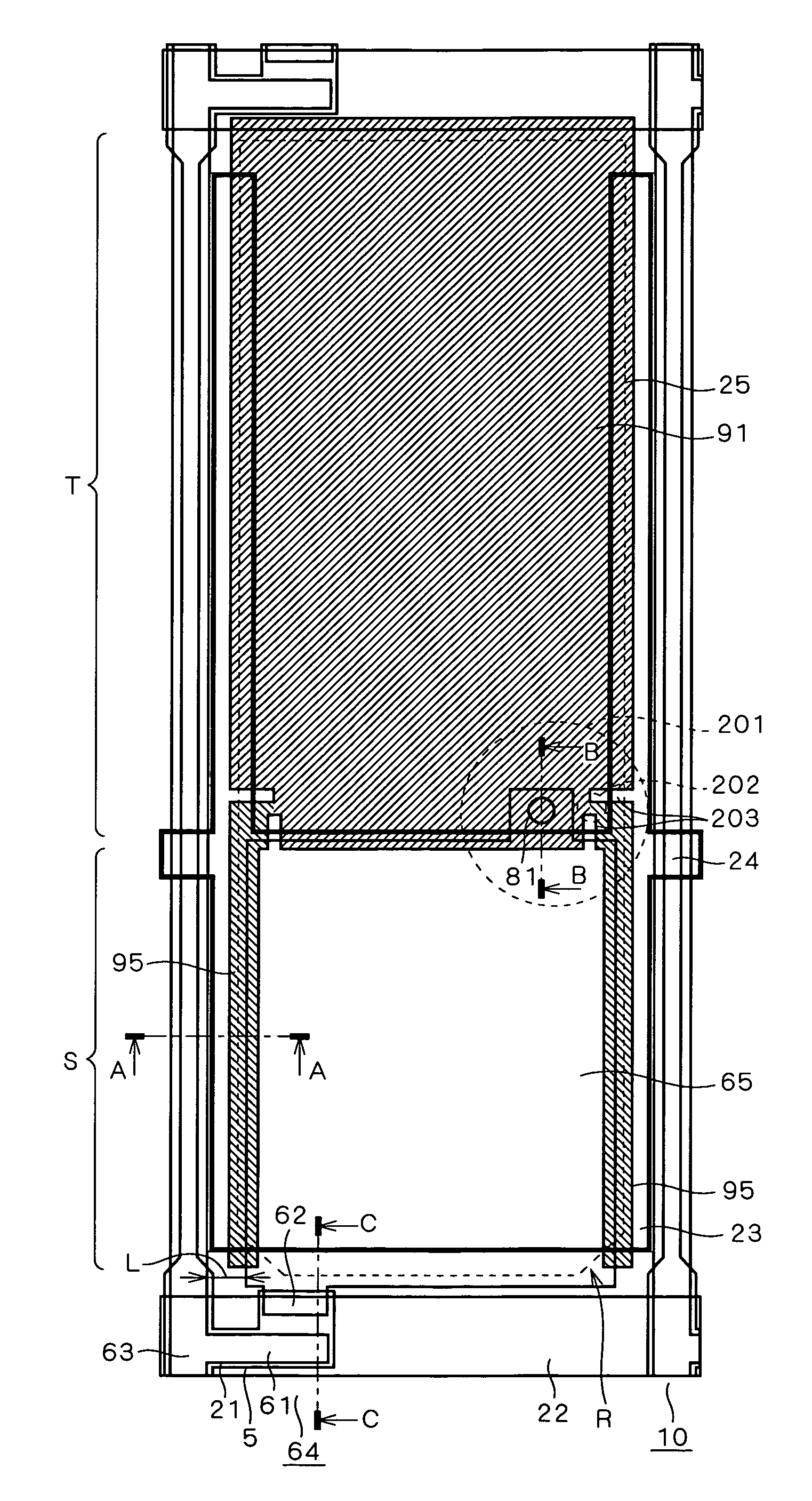
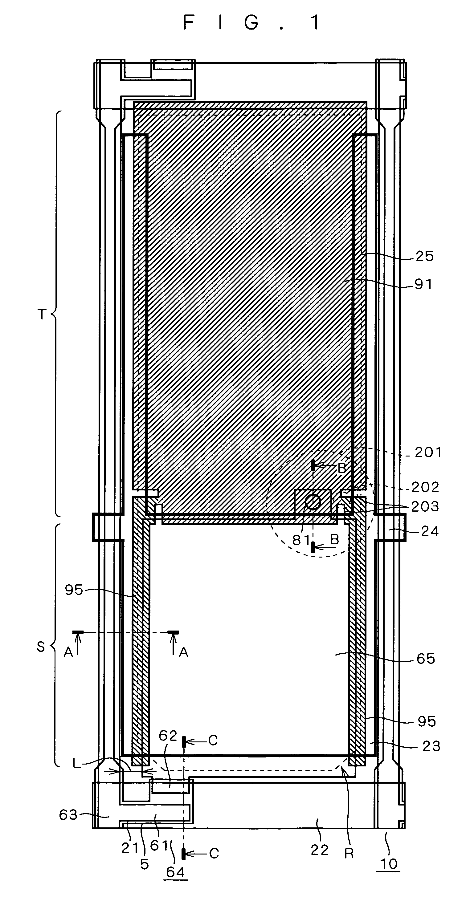
[0009]In a semi-transparent liquid crystal display in which a source wiring and a reflective pixel electrode are formed in the same layer, it is an object of the present invention to avoid reflective contrast reduction even when the source wiring and the reflective pixel electrode are spaced apart from each other, while allowing the semi-transparent liquid crystal display to repair a point defect without causing a short circuit between a transparent pixel electrode and an auxiliary capacitive wiring.
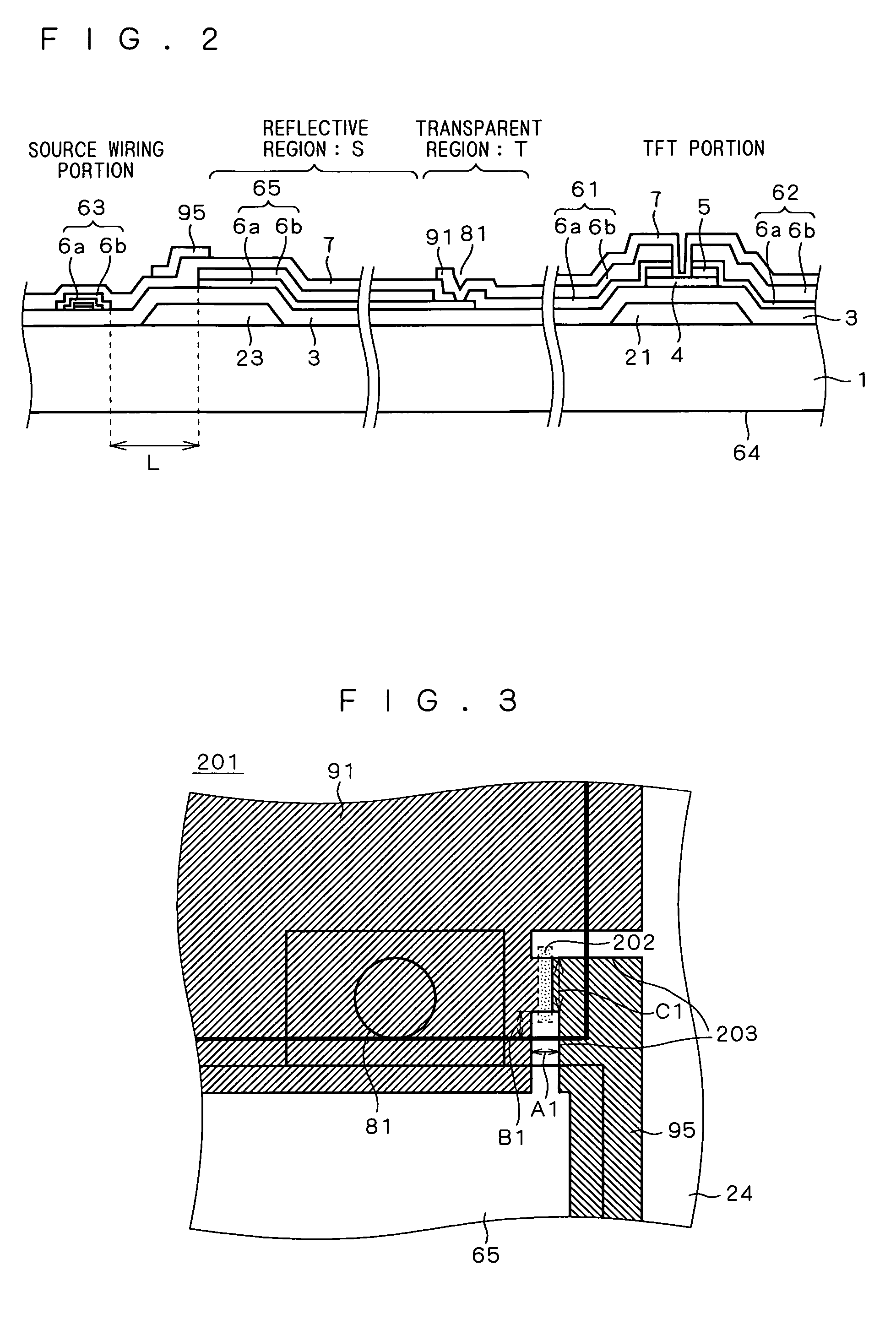
[0011]As a result of the existence of the contrast reduction preventive electrode, an electric field is applied to a liquid crystal layer between the contrast reduction preventive electrode and an opposed electrode. This prevents reflected light from the auxiliary capacitive electrode from appearing on a display screen to thereby provide excellent display characteristic with high reflective contrast. Further, a connection for connecting the contrast reduction preventive electrode and the transparent pixel electrode is formed, in such a position that the connection does not overlap the auxiliary capacitive wiring in plan view. Hence, when the contrast reduction preventive electrode is cut off at the connection with the transparent pixel electrode, the transparent pixel electrode is prevented from being short circuited with the auxiliary capacitive wiring.

Problems solved by technology

On the other hand, due to the arrangement of the contrast reduction preventive electrode in the uppermost layer of the reflective region, the surface of the opposed electrode and the surface of the contrast reduction preventive electrode may be short circuited due to the existence of a foreign conductive substance therebetween, for example.
As a result, a corresponding pixel becomes a point defect.
A pixel subjected to the short circuit generates a black dot defect in the case of N / B (normally black) which does not allow passing of light when no voltage is applied.
Thus the generation of a short circuit results in the generation of a spot defect.
This results in reflective contrast reduction.

Method used


Image

  • Semi-transparent TFT array substrate, and semi-transparent liquid crystal display with transparent pixel electrode and contrast reduction preventive electrode connected in the same layer
  • Semi-transparent TFT array substrate, and semi-transparent liquid crystal display with transparent pixel electrode and contrast reduction preventive electrode connected in the same layer
  • Semi-transparent TFT array substrate, and semi-transparent liquid crystal display with transparent pixel electrode and contrast reduction preventive electrode connected in the same layer

Examples


first preferred embodiment

[0023]In a semi-transparent liquid crystal display according to the background art of the present invention, a contrast reduction preventive electrode is provided in the uppermost layer of a reflective region in a TFT array substrate. The contrast reduction preventive electrode is arranged between a source wiring and a reflective pixel electrode.

[0024]An electric field is applied to a liquid crystal layer between the contrast reduction preventive electrode and an opposed electrode by the formation of the contrast reduction preventive electrode. This prevents reflected light from an auxiliary capacitive electrode from appearing on a display screen to thereby provide excellent display characteristic with high reflective contrast.

[0025]On the other hand, due to the arrangement of the contrast reduction preventive electrode in the uppermost layer of the reflective region, the surface of the opposed electrode and the surface of the contrast reduction preventive electrode may be short cir...

second preferred embodiment

[0104]FIG. 14 is an enlarged top view showing the TFT array substrate 10 constituting a semi-transparent liquid crystal display according to a second preferred embodiment of the present invention.

[0105]In the TFT array substrate 10 of the second preferred embodiment, the pair of slits 203 (see FIGS. 1 and 3) is replaced by slits 205 formed in the auxiliary capacitive wiring 24.

[0106]The connection 202 for connecting the contrast reduction preventive electrode 95 and the transparent pixel electrode 91 is arranged such that the connection 202 corresponds in position to the slits 205 formed in the auxiliary capacitive wiring 24 in plan view.

[0107]Thus the auxiliary capacitive wiring 24 does not overlap the connection 202.

[0108]The other structures are the same as those of the first preferred embodiment, and will not be repeatedly discussed.

[0109]In the steps of manufacturing a panel, laser repair process is performed while viewing an image of the rear surface of the TFT array substrate...

third preferred embodiment

[0116]FIG. 15 is an enlarged top view showing a connection formed in a transparent pixel electrode of the TFT array substrate 10 that constitutes a semi-transparent liquid crystal display according to a third preferred embodiment of the present invention.

[0117]The TFT array substrate 10 of the third preferred embodiment is a combination of the TFT array substrate 10 of the first preferred embodiment and that of the second preferred embodiment. The same structures as those of the first or second preferred embodiment are designated by the same reference numerals, and will not be repeatedly discussed.

[0118]With reference to FIG. 15, the pair of slits 203 is formed in the transparent pixel electrode 91 or the contrast reduction preventive electrode 95. Further, the slits 205 are formed in the auxiliary capacitive wiring 24.

[0119]The TFT array substrate 10 of the third preferred embodiment is formed by incorporating the pair of slits 203 in the transparent pixel electrode 91 or the contr...


PUM

PropertyMeasurementUnit
distanceaaaaaaaaaa
thicknessaaaaaaaaaa
thicknessaaaaaaaaaa

Abstract

A semi-transparent TFT array substrate has a TFT including a source electrode, a gate electrode, and a drain electrode. The substrate also has an auxiliary capacitive wiring and a reflective pixel electrode. Further, the substrate has a transparent pixel electrode including an electrode extending from a corner of the rest of the transparent pixel electrode to an edge of the auxiliary capacitive wiring closest to a gate wiring connected to the gate electrode. In addition, the substrate has a source wiring connected to the source electrode. The auxiliary capacitive wiring overlaps a space existing between the reflective pixel electrode and the source wiring. The electrode is disposed between the reflective pixel electrode and the source wiring. A connection which connects the electrode and the rest of the transparent pixel electrode does not overlap the auxiliary capacitive wiring in a plan view. The connection does not overlap the gate wiring.

Description

BACKGROUND OF THE INVENTION[0001]1. Field of the Invention[0002]The present invention relates to an active matrix type liquid crystal display intended for use as a display device in an OA device and the like for displaying images and character information. More specifically, the present invention relates to a semi-transparent liquid crystal display with a transparent region for allowing light to pass through a pixel region, and a reflective pixel electrode for reflecting ambient light.[0003]2. Description of the Background Art[0004]In a semi-transparent TFT (thin-film transistor) array substrate (which will also be referred to simply as “TFT array substrate”) adopted in a commonly-used conventional semi-transparent liquid crystal display, a transparent region for allowing backlight on the rear side of a display screen to pass therethrough, and a reflective region for reflecting ambient light entering a liquid crystal layer are formed in each pixel.[0005]As a known structure and a ma...

Claims


Application Information

Patent Timeline
Patent Type & Authority Patents(United States)
IPC IPC(8): G02F1/1343
CPCG02F1/133555G02F1/136213G02F1/136259G02F1/1343
Inventor YAMASHITA, SHINJIMASUTANI, YUICHINAGANO, SHINGO
Owner MITSUBISHI ELECTRIC CORP
Learn More