
Method and apparatus for generating synchronization signals for synchronizing multiple chips in a system

a technology of synchronization signals and chips, applied in the direction of generating/distributing signals, synchronization signal speed/phase control, digital transmission, etc., can solve the problem of insufficient time, and achieve the effect of reducing timing uncertainty in cross-chip communication systems

Inactive Publication Date: 2010-11-02
INT BUSINESS MASCH CORP
View PDF5 Cites 4 Cited by
  • Summary
  • Abstract
  • Description
  • Claims
  • Application Information

AI Technical Summary

Benefits of technology

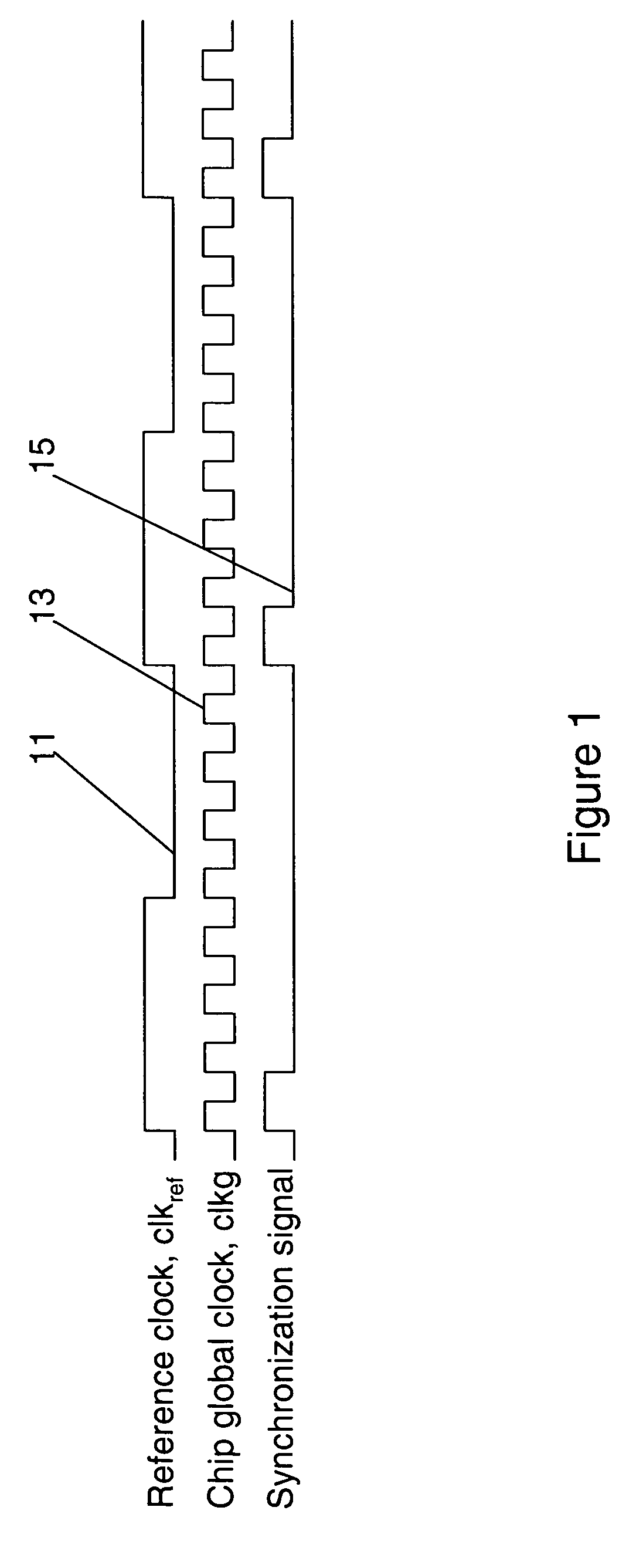
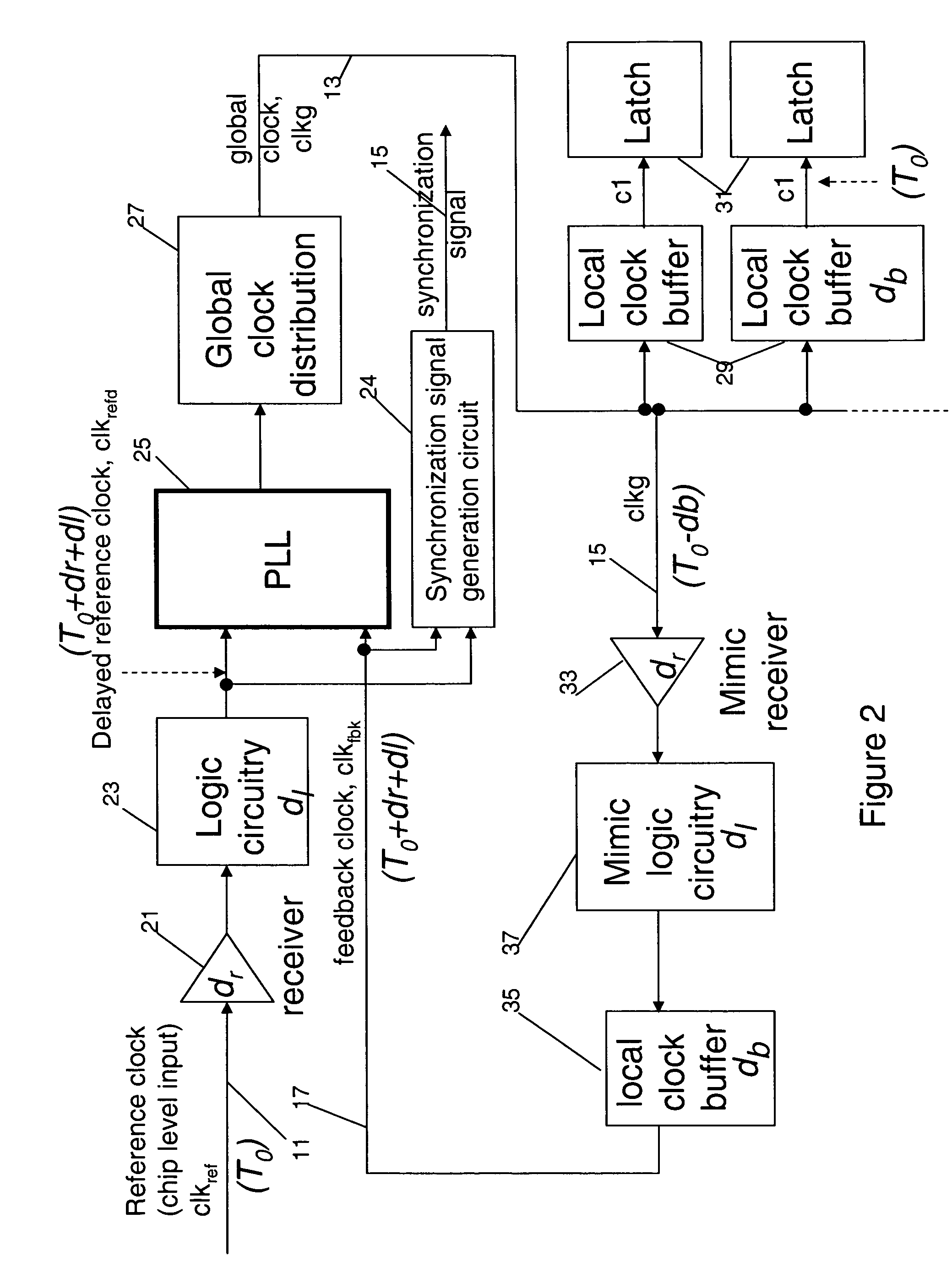
[0006]The generation of the synchronization signal from reference clock and chip global clock may be done with edge detection logic at slower frequency. In high performance server system design with multiple chips, a common practice for server systems is to use feedback clock, clkfbk 17 and delayed reference clock, to generate the synchronization signal as shown in FIG. 2. This is because the phases of these two clocks are known to align well to each other. The synchronization generation logic may be embedded in the PLL 25 design to work with other aspects of PLL functions. The feedback clock path includes a mimic receiver 33, mimic logic 35, and mimic local clock buffer 37. The purpose of these mimic circuits is to align the phase of local clock buffer output, c1, to the phase of input reference clock 11. The parentheses in FIG. 2 indicate the relative timing to input reference clock at different nodes. By doing so, all the chips in the same system receiving reference clocks with the same phase will have c1 clocks, which clock the latches, phase-aligned to each other. This reduces timing uncertainty in cross-chip communication systems.
[0016]As a result of the summarized invention, technically we have achieved a solution which resolves clock signal uncertainty and facilitates the synchronization signals to be generated deterministically independent of the chip global clock cycle time.

Problems solved by technology

But, as shown in FIG. 3, when the total delay of mimic circuitry in FIG. 2, td, is close to one clkg cycle, there won't be enough time, ttr, for the synchronization signal to be transferred to the first latch.

Method used


Image

  • Method and apparatus for generating synchronization signals for synchronizing multiple chips in a system
  • Method and apparatus for generating synchronization signals for synchronizing multiple chips in a system
  • Method and apparatus for generating synchronization signals for synchronizing multiple chips in a system

Examples


embodiment i

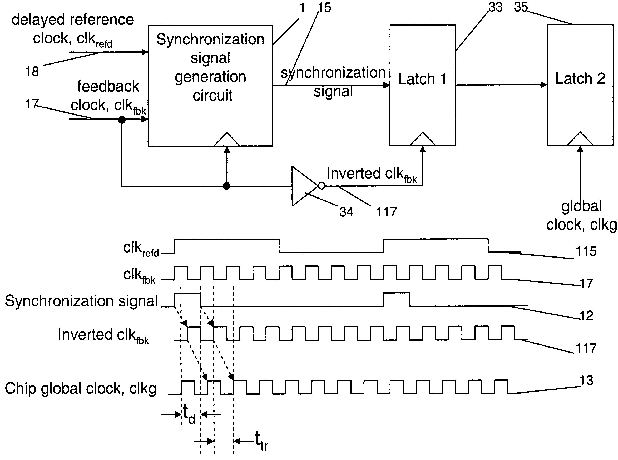
[0030]When the delay of the mimic circuitry is around 1 clkg cycle but less than 1.5 clkg cycles, the first latch to receive the synchronization signal is placed close to the synchronization signal generation circuit. The feedback is inverted and used to clock latch 1 as shown in FIG. 4. The output from the synchronization signal generation circuit is still launched with feedback clock. Effectively, this scheme borrows 0.5 clkg cycle from the next path between latch 1 and latch 2, so latch 1 to latch 2 becomes a half-cycle path. In physical design, latch 2 also need to be placed close to latch one to allow the half cycle path.

[0031]Other variations to this scheme include using inverted feedback clock to clock the synchronization generation circuit as shown in FIG. 7a. By doing so, the path between the launching latches and latch 1 receive one full cycle for signal transfer. This allow additional combinational logic to be added to the path for other functions.

embodiment ii

[0032]When, td is more than 1.5 times of the minimum global clock cycle time, even the approach used by embodiment I is not adequate to receive the synchronization signal at the second latch, clocked by clkg, without uncertainty. When the chip runs at slower frequency than the maximum frequency, the cycle relative to clkg that the synchronization signal is latched at latch 2 may become uncertain if the mimic circuitry delay, td, is close to the integral multiple of slowed down clkg cycle time as shown in FIG. 6. It is critical that the method used will operate at the maximum frequency and any frequency that is slower than the design frequency. In today's modern processors, the frequency of operation is often slowed down to save power, to prevent over heating, for speed sorting, or for testing. The system must continue to function under these slower frequencies.

[0033]To make the design frequency independent, we'll need to generate the synchronization signal with two other clock sourc...


PUM


Abstract

A clock generator circuit for generating synchronization signals for a multiple chip system. The clock generator circuit comprises generation of a synchronization signal from a reference clock and chip global clock with edge detection logic. In high performance server system design with multiple chips, a common practice for server systems is to use feedback clock and delayed reference clock to generate the synchronization signal. The generated synchronization signal is transferred to latches clocked by the global clock to be used for chip synchronization functions. As the system clock frequency is pushed higher, the phase difference between generated synchronization signal clocked by feedback clock and receiving latch clocked by global clock is becoming such a large portion of cycle time that this signal cannot be transferred deterministically. This invention resolves the uncertainty problem and allows the synchronization signals to be generated deterministically independent of the chip global clock cycle time.

Description

CROSS-REFERENCE TO RELATED APPLICATIONS[0001]This is a continuation in part of commonly assigned, U.S. patent application Ser. No. 11 / 056,767 filed Feb. 11, 2005 now U.S. Pat. No. 7,382,844 for Methods to Self-synchronize Clocks on Multiple Chips in a System.BACKGROUND[0002]1. Field of the Invention[0003]This invention relates to methods to self-synchronize clocks on multiple chips in a system[0004]2. Description of Background[0005]In a synchronous digital system comprised of multiple chips with synchronous communications among them, cross-chip functions often require a synchronized “time-zero” over a certain predefined number of clock cycles. To properly synchronize the time-zero of all the chips in the same system, a method is required to synchronize the counters that keep track of the “time-zero” on all the chips. One way to accomplish this is through the methods described in patent application Ser. No. 11 / 056,767, Methods to Self-synchronize Clocks on Multiple Chips in a System....

Claims


Application Information

Patent Timeline
Patent Type & Authority Patents(United States)
IPC IPC(8): H04L7/00
CPCG06F1/10H03L7/06
Inventor HWANG, CHARLIE C.BECKER, WIREN D.MCNAMARA, TIMOTHY G.TONG, CHING-LUNG
Owner INT BUSINESS MASCH CORP
Learn More