

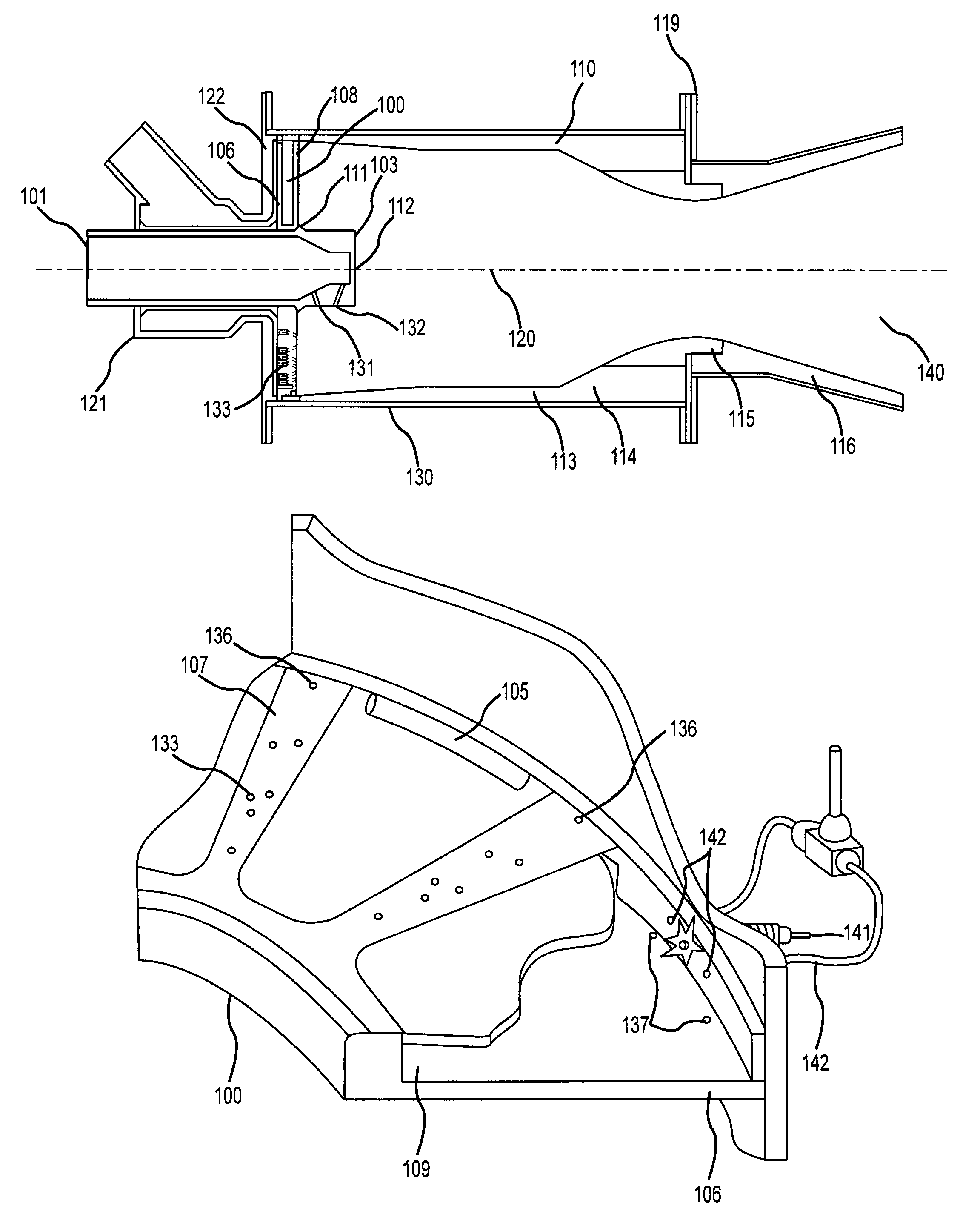
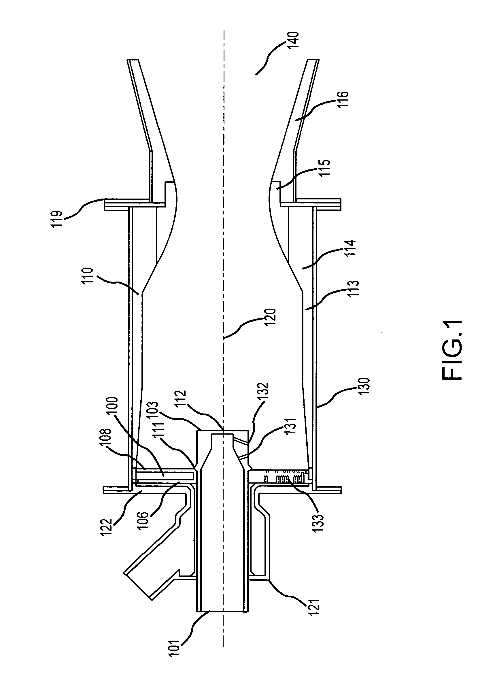
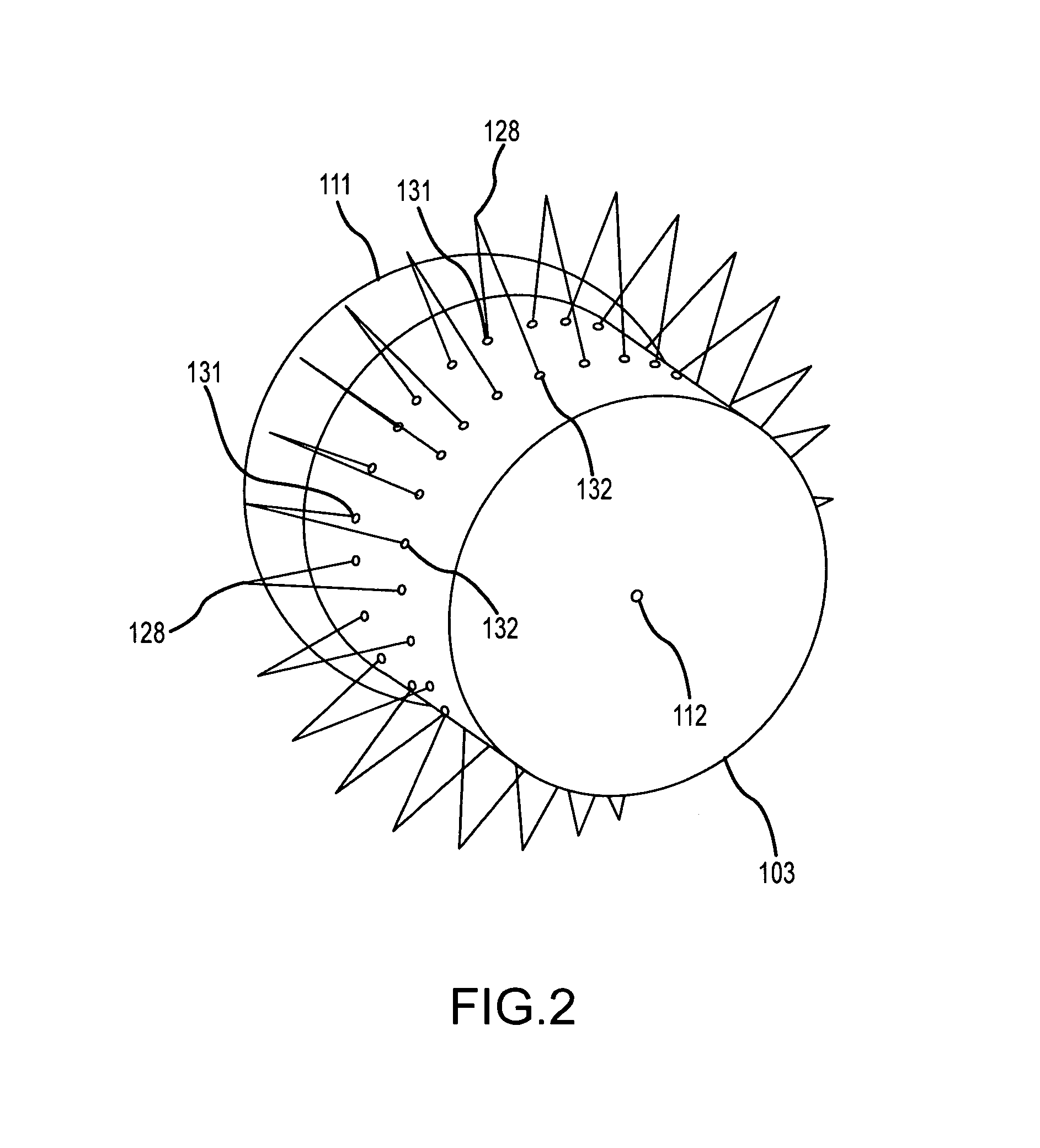
Liquid propellant rocket engine with pintle injector and acoustic dampening
a propellant rocket and injector technology, applied in the field of aerospace propulsion systems, can solve the problems of increasing the likelihood of engine failure, affecting the efficiency of the engine, and affecting so as to improve the stability of the combustion cycle and reduce the harmonic disturbance
- Summary
- Abstract
- Description
- Claims
- Application Information
AI Technical Summary
Benefits of technology
Problems solved by technology
Method used
Image

Examples
Embodiment Construction
[0029]A preferred embodiment of the present invention is illustrated in FIGS. 1-6. It is to be expressly understood that the descriptive embodiment is provided herein for explanatory purposes only and is not meant to unduly limit the claimed inventions. Other embodiments of the present invention are considered to be within the scope of the claimed inventions, including not only those embodiments that would be within the scope of one skilled in the art, but also as encompassed in technology developed in the future. Although liquid oxygen and kerosene are often used as an exemplar combination in describing this invention, it is merely one example of said combination. Liquid oxygen and kerosene is discussed primarily for the purposes of understanding the system and method application. It is to be expressly understood that other oxidizers and propellants are considered to be within the scope of the present invention as well.
[0030]As will be understood by those familiar with the art, the...
PUM
 Abstract
Description
Claims
Application Information