Power steering system
a technology of power steering and transmission mechanism, which is applied in the direction of power steering, electric steering, vehicle components, etc., can solve the problems that the impact of a peripheral component on the steering transmission mechanism cannot be surely detected, and the eps mechanism itself cannot be accurately detected, so as to achieve the effect of more accurate detection of the impact on the steering transmission mechanism
- Summary
- Abstract
- Description
- Claims
- Application Information
AI Technical Summary
Benefits of technology
Problems solved by technology
Method used
Image
Examples
first embodiment
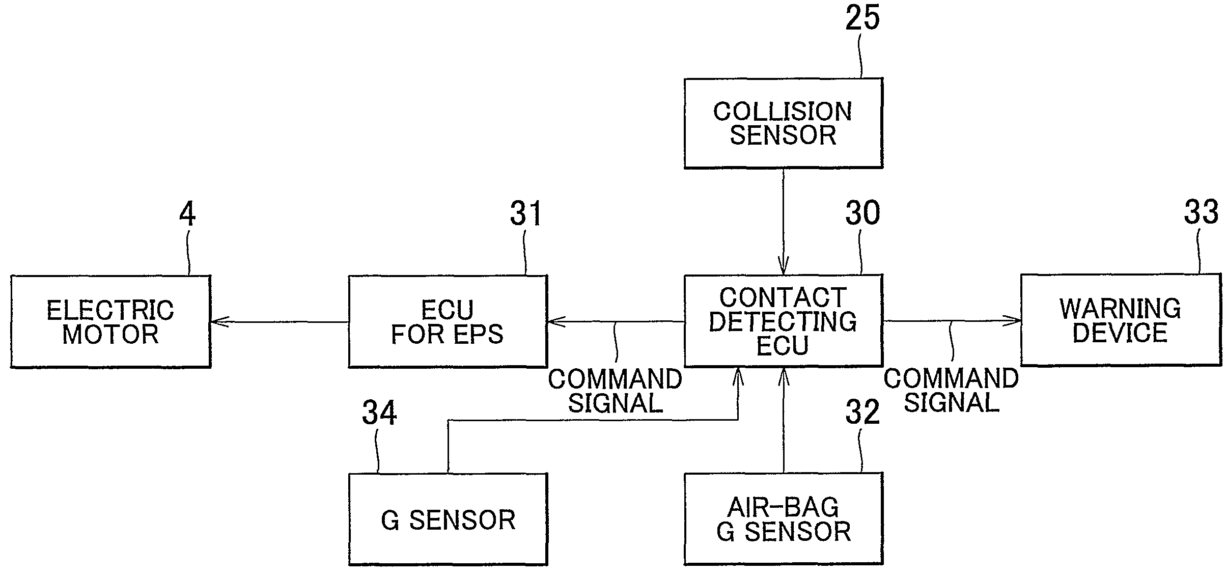
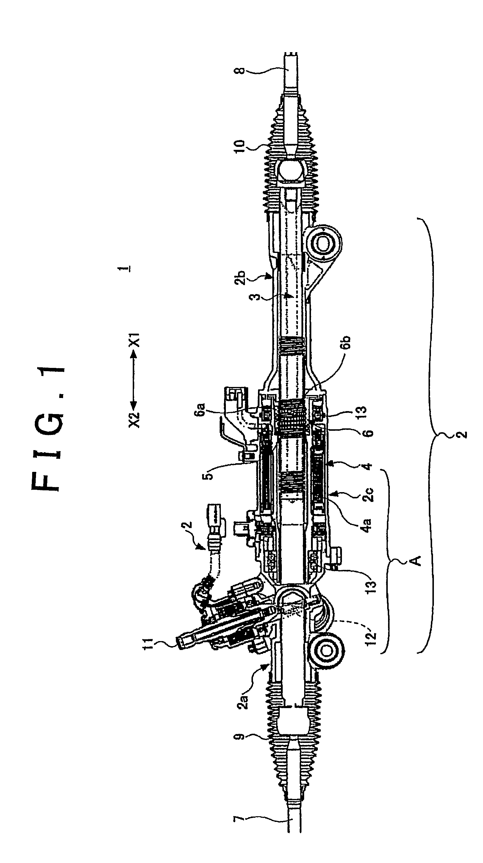
[0061]The first embodiment relates to a case where the rotational angle sensor 60 of the assist motor 4 is effectively used to detect the impact of a peripheral component on the power steering system 1 (in particular, the part thereof around the assist motor).
[0062]FIGS. 5A and 5B are a side view and a plan view, respectively, which schematically show the impact of a peripheral component on the part of the power steering system 1 around the assist motor (see FIG. 3).
[0063]In the example shown in FIGS. 5A and 5B, the left direction in FIGS. 5A and 5B is the forward direction of the vehicle, and the peripheral component, such as an engine, is placed at the rear of the gear box of the power steering system 1. The gear box of the power steering system 1 is fastened to a body frame (the suspension member) at two points along the lateral direction of the vehicle with bushings, for example, interposed therebetween. With regard to the example shown in FIGS. 5A and 5B, there is a possibility...
second embodiment
[0071]A second embodiment relates to a case where the rotational angle sensor 60 of the assist motor 4 is effectively used to detect the impact of a peripheral component on the power steering system 1 (in particular, the part thereof around the assist motor), paying appropriate attention to the possibility that the angular speed of the rotor 5 varies due to the backward input from the wheels.
[0072]When the backward input from the wheels is applied, the linear motion of the rack bar 3 (the movement of the shaft 3a in the axial direction) is caused, which in turn causes the rotor 5 to rotate through the medium of the ball screw nut 6a. Also in this case, the angular speed of the rotor 5 varies. Accordingly, it is necessary to avoid erroneously determining that the impact of a peripheral component on the power steering system 1 has occurred, in response to such variation of the angular speed.
[0073]FIG. 7 is a diagram showing a time-series waveform of the angular speed signal ω (the sig...
third embodiment
[0082] it is made possible to detect the variation of the angular speed of the rotor 5 caused by the impact of the peripheral component on the power steering system 1 with high accuracy, wherein the variation of the angular speed of the rotor 5 caused by the backward input from the wheels is discriminated therefrom. In addition, because the determination is triggered when the angular speed ω of the rotor 5 exceeds the predetermined impact determination threshold value ωa1, it is possible to reduce the load of making the determination.
[0083]In the third embodiment, from the same viewpoint, the frequency component within the first frequency band of the angular speed signal ω sampled during a predetermined sampling time period may be extracted to determine whether the peak of the extracted angular speed signal ω exceeds a predetermined impact determination threshold value. If the peak of the extracted angular speed signal ω exceeds the impact determination threshold value, the impact d...
PUM
 Abstract
Description
Claims
Application Information
 - R&D
- Intellectual Property
- Life Sciences
- Materials
- Tech Scout
- Unparalleled Data Quality
- Higher Quality Content
- 60% Fewer Hallucinations
Browse by: Latest US Patents, China's latest patents, Technical Efficacy Thesaurus, Application Domain, Technology Topic, Popular Technical Reports.
© 2025 PatSnap. All rights reserved.Legal|Privacy policy|Modern Slavery Act Transparency Statement|Sitemap|About US| Contact US: help@patsnap.com


