System for controlling electric device

a technology for electric devices and control circuits, applied in the direction of shock absorbers, pulse manipulation, pulse techniques, etc., can solve the problems of inaccurate current detection, electromagnetic noise can interfere with radio signal reception, and decrease the durability of current detection circuits, so as to suppress electromagnetic nois

Inactive Publication Date: 2010-11-09
HONDA MOTOR CO LTD +1
View PDF4 Cites 13 Cited by
  • Summary
  • Abstract
  • Description
  • Claims
  • Application Information

AI Technical Summary

Benefits of technology

[0007]A second object of the present invention is to provide a system for controlling an electric device that can suppress electromagnetic interference by using an LC filter while avoiding decrease in the detection accuracy and durability of a current detection portion.
[0016]In this way, the LC filter can suppress electromagnetic noises related to turning on / off of the switch circuit (pulse width modulation circuit) and even if the LC filter undergoes resonance, the current detection portion will not be undesirably affected by the resonance because the current detection portion is located at an upstream of the LC filter. Further, in such a structure, a capacitor in the LC filter may store and discharge electric current along with turning on / off of the switch portion but the accumulated value of the electric current output from the current detection portion may not be affected by the electric current stored to and discharged from the capacitor. Thus, controlling the pulse width modulation circuit based on the accumulated value of the electric current can allow accurate control of the electric current actually supplied to the electric device.

Problems solved by technology

As a result, electromagnetic noises having frequencies of multiples of the PWM signal frequency (e.g., 20 kHz) are generated from the wirings for conducting electric current supplied from the control device to the variable damping force damper, and the electromagnetic noises can interfere with radio signal reception or the like.
However, a resonance at a certain frequency cannot be avoided in the LC filter, and as a result, the current detection circuit may be applied with a signal beyond its detection range and this can lead to inaccurate current detection or decrease in durability of the current detection circuit.
Further, in the case where the resonance of the LC filter occurs at a frequency near the control frequency of the variable damping force damper, the control can be disturbed by the resonance and this can unfavorably affect the behavior of the motor vehicle.

Method used


Image

  • System for controlling electric device
  • System for controlling electric device
  • System for controlling electric device

Examples


Embodiment Construction

[0026]Now, the present invention is described in detail in terms of a concrete embodiment in which the present invention is applied to a rear suspension system of a four-wheel motor vehicle.

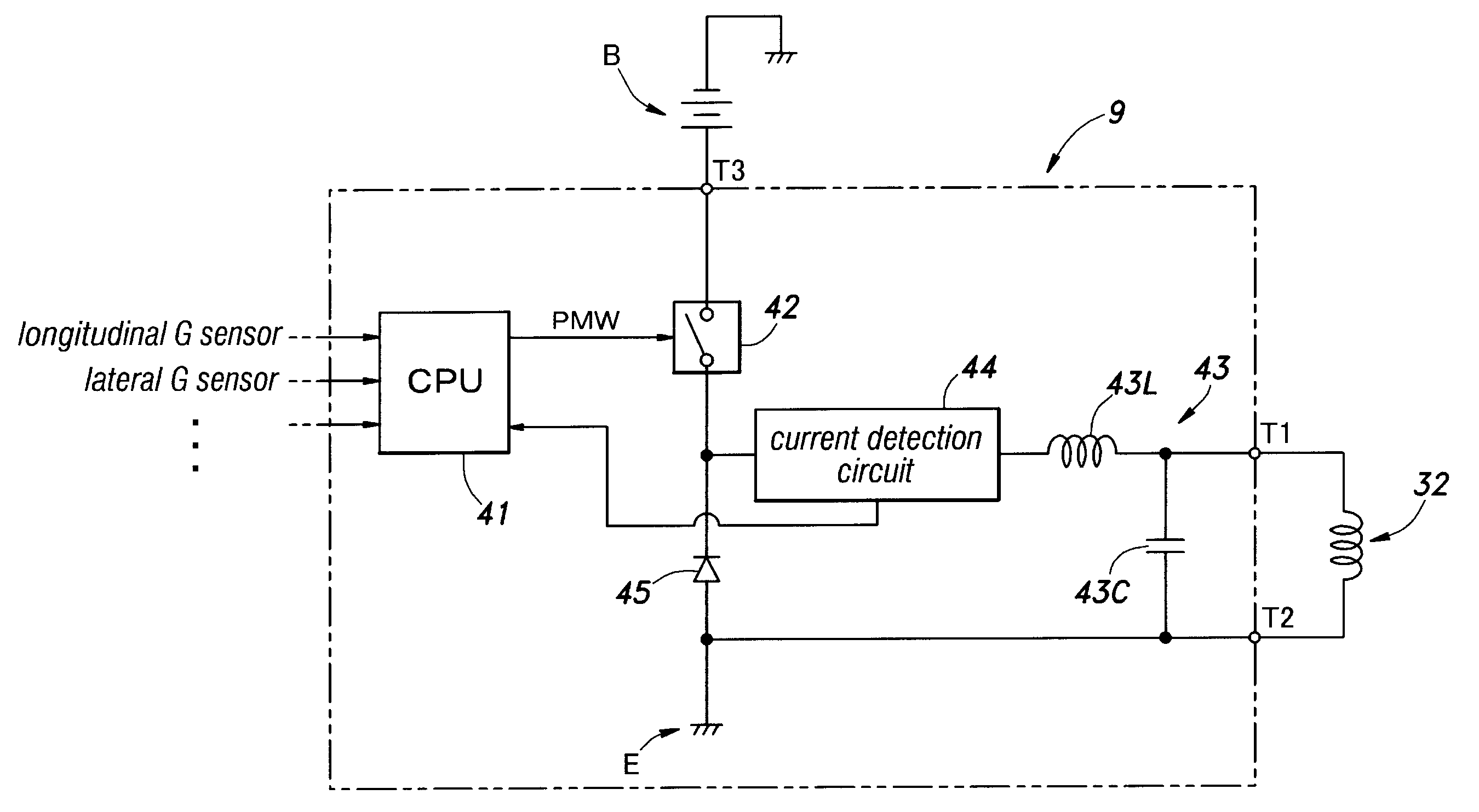
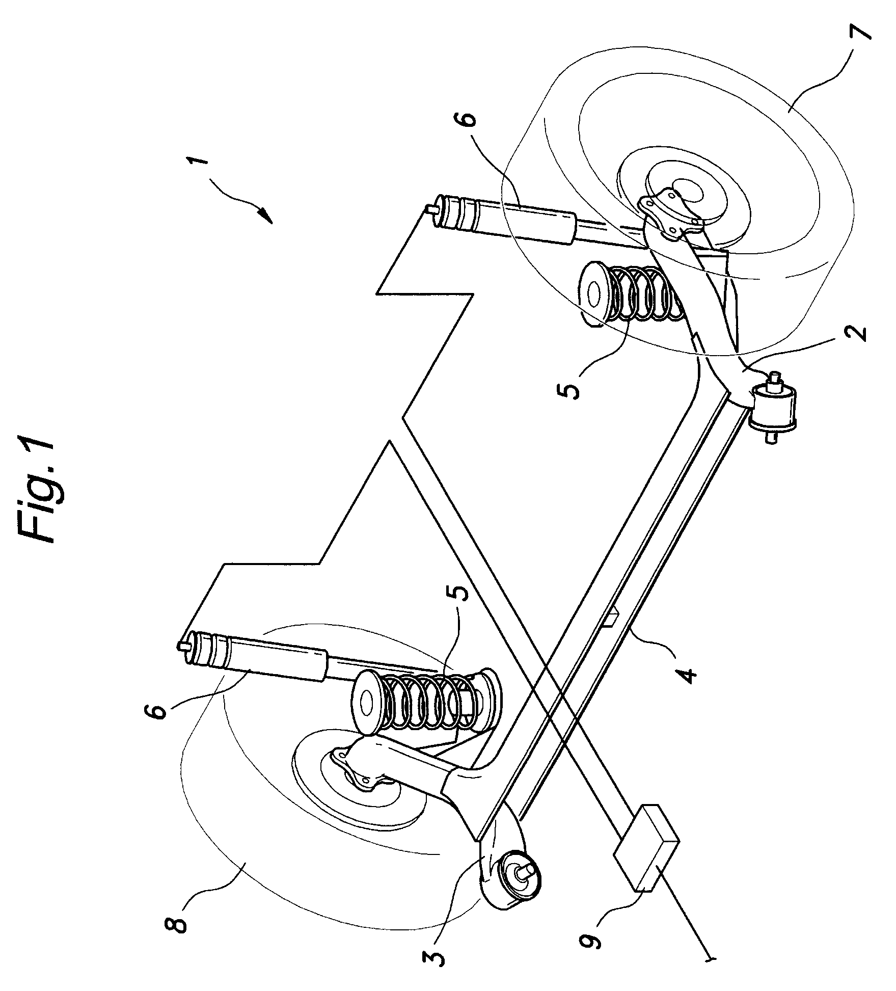
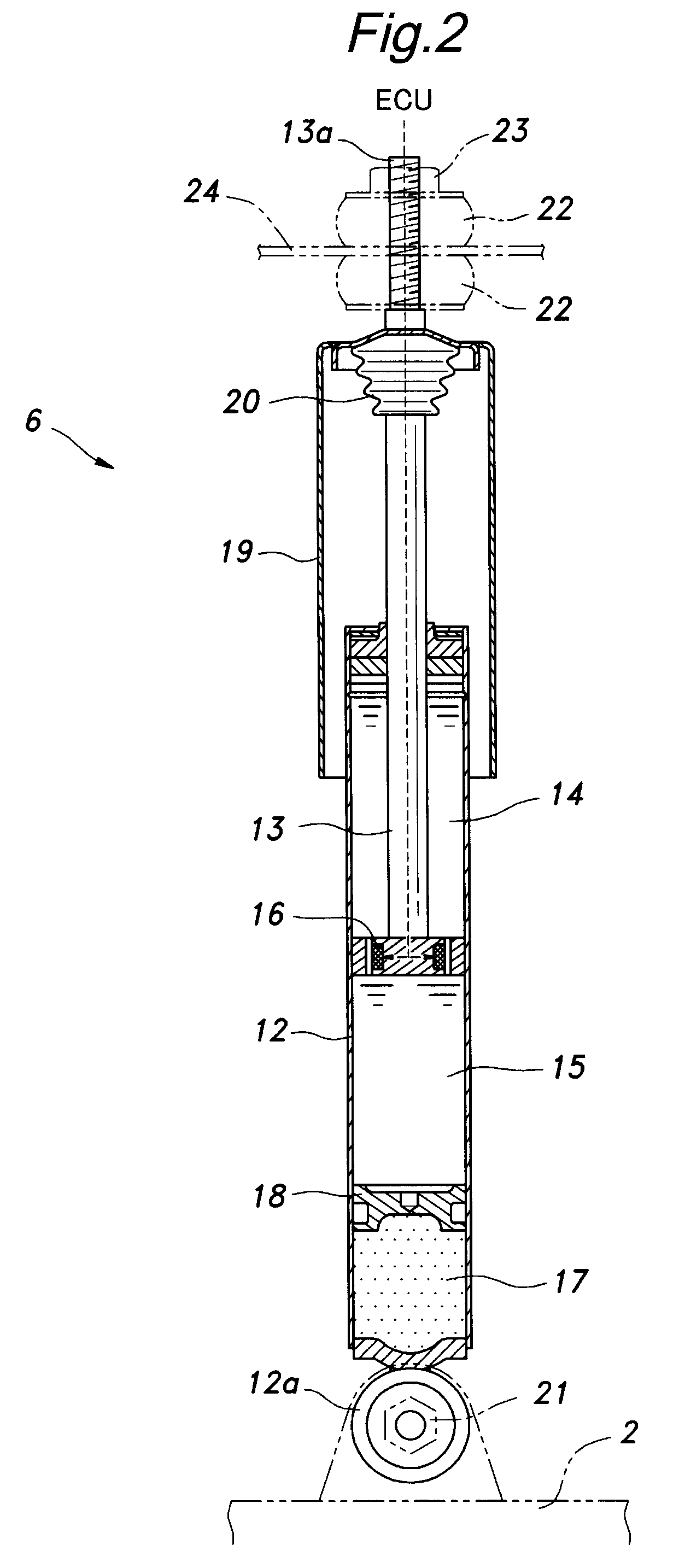
[0027]FIG. 1 is a perspective view of the rear suspension system, FIG. 2 is a longitudinal cross-sectional view of a damper, FIG. 3 is a general structural view of an MLV (Magnetizable Liquid Valve), and FIG. 4 is a structural view of an essential part of a damper control circuit according to an embodiment of the present invention.

[0028]As shown in FIG. 1, a rear suspension 1 of this embodiment of the present invention consists of a so-called H-shaped torsion beam suspension, comprising: left and right trailing arms 2, 3; a torsion beam 4 connecting middle portions of the trailing arms 2, 3 to each other; left and right coil springs 5 serving as suspension springs; and left and right dampers 6 provided on either side, to whereby support left and right rear wheels 7, 8. Each damper 6 consists of a...


PUM


Abstract

A system for controlling an electric device comprises: a power supply for supplying electric power to an electric device; switch portion connected between the power supply and the electric device for controlling the electric power supplied to the electric device; an LC filter disposed between the switch portion and the electric device; and current detection portion for detecting an electric current supplied to the electric device.

Description

TECHNICAL FIELD[0001]The present invention relates to a system for controlling an electric device, and more specifically relates to a technology for suppressing electromagnetic interference by using an LC filter while avoiding decrease in detection accuracy and durability of a current detection portion.BACKGROUND OF THE INVENTION[0002]A suspension is an important element of a motor vehicle and significantly influences the traveling stability and riding comfort of the motor vehicle. The suspension mainly consists of a link (arm, rod and the like) for supporting a tire to a vehicle body in a vertically moveable fashion, a spring for absorbing an impact from a road surface by deformation, and a damper for damping the vertical oscillation of the vehicle body. As a damper in such a suspension system, a so-called cylinder-type damper is widely used. A cylinder-type damper mainly consists of a cylinder tube filled with a hydraulic oil and a piston rod having a piston at its end, wherein th...

Claims


Application Information

Patent Timeline
Patent Type & Authority Patents(United States)
IPC IPC(8): F16F15/03
CPCB60G13/08B60G17/08F16F9/535B60G2202/24B60G2202/25
Inventor SEKIYA, SHIGENOBUICHIKAWA, TOMOYUKIIWAGAMI, NAOKI
Owner HONDA MOTOR CO LTD
Why Eureka
Try Eureka