Dual drive drywall lift system

a technology of drywall and lift system, which is applied in the field of dual-drive drywall lift system, can solve the problem of not offering a lift system

Inactive Publication Date: 2010-11-09
TELPRO
View PDF11 Cites 19 Cited by
  • Summary
  • Abstract
  • Description
  • Claims
  • Application Information

AI Technical Summary

Benefits of technology

[0015]A further object is to provide a dual drive drywall lift system that incl

Problems solved by technology

The prior lifts systems do not offer a lift system that may utilize an external

Method used


Image

  • Dual drive drywall lift system
  • Dual drive drywall lift system
  • Dual drive drywall lift system

Examples


Embodiment Construction

A. Overview

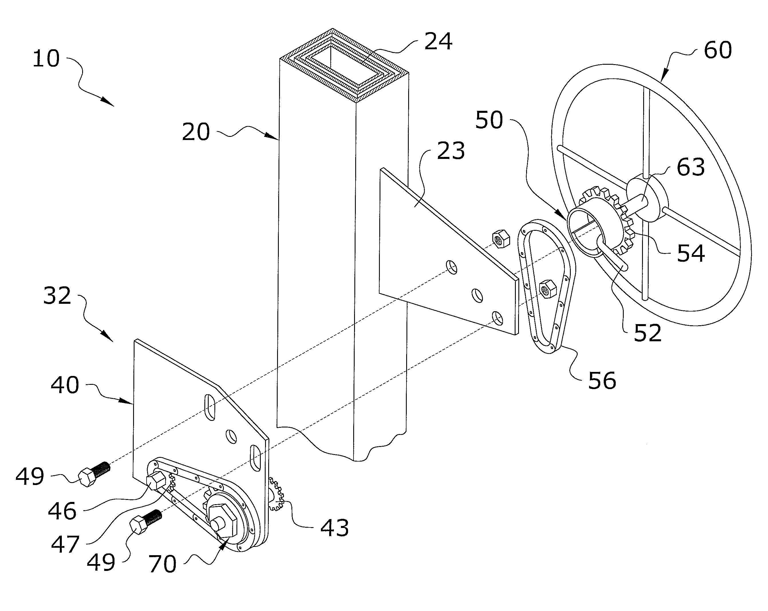
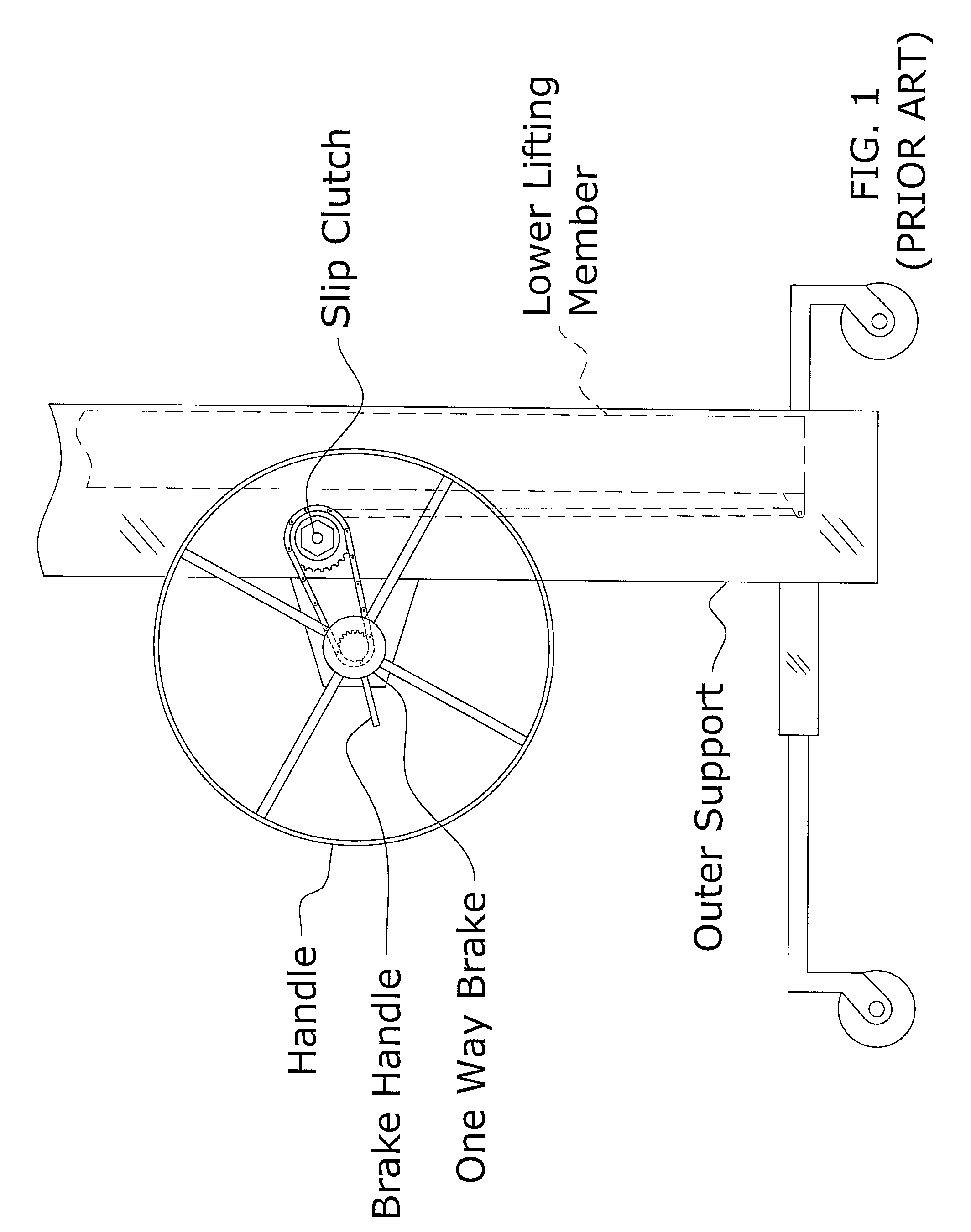
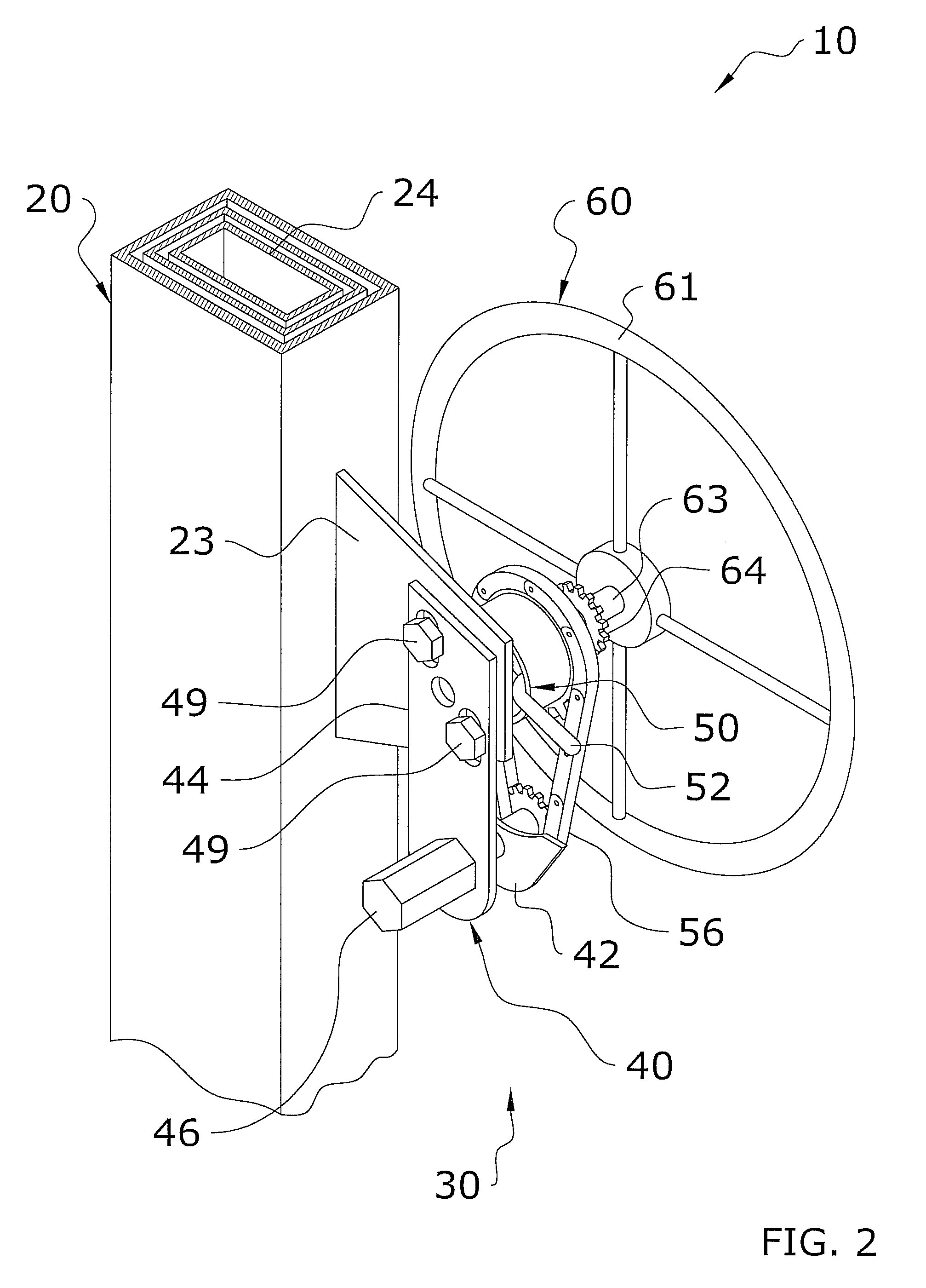
[0031]Turning now descriptively to the drawings, in which similar reference characters denote similar elements throughout the several views, FIGS. 1 through 13 illustrate a dual drive drywall lift system 10, which comprises a lifting unit including at least one telescoping member 24, a first drive unit 60 mechanically connected to the lifting unit, wherein the first drive unit 60 selectively extends and retracts the telescoping member(s) 24 outwardly via a manual force input member and a second drive unit 46 mechanically connected to the lifting unit, wherein the second drive unit 46 selectively extends and retracts the telescoping member(s) 24 outwardly via a powered force applied to the second drive unit 46.

B. Telescoping Drywall Lifter

[0032]The telescoping drywall lifter (i.e. lifting unit) is capable of lifting and lowering a load 12, such as but not limited to a drywall panel (e.g. plasterboard, paneling, wooden panels, composite panels, bricks and the like). The tel...


PUM


Abstract

A dual drive drywall lift system for efficiently lifting a panel either manually or through an external motor. The dual drive drywall lift system generally includes a lifting unit including at least one telescoping member, a first drive unit mechanically connected to the lifting unit, wherein the first drive unit selectively extends and retracts the telescoping member(s) outwardly via a manual force input member and a second drive unit mechanically connected to the lifting unit, wherein the second drive unit selectively extends and retracts the telescoping member(s) outwardly via a powered force applied to the second drive unit.

Description

CROSS REFERENCE TO RELATED APPLICATIONS[0001]Not applicable to this application.STATEMENT REGARDING FEDERALLY SPONSORED RESEARCH OR DEVELOPMENT[0002]Not applicable to this application.BACKGROUND OF THE INVENTION[0003]1. Field of the Invention[0004]The present invention relates generally to a lift system and more specifically it relates to a dual drive drywall lift system for efficiently lifting a panel either manually or through an external motor.[0005]2. Description of the Related Art[0006]Any discussion of the prior art throughout the specification should in no way be considered as an admission that such prior art is widely known or forms part of common general knowledge in the field.[0007]Lift systems have been in use for years. Typically, lift systems are comprised of a telescoping structure and may be utilized for various purposes, such as but not limited to elevating a drywall panel. The panel is generally positioned upon the upper end of the telescoping structure, wherein the...

Claims


Application Information

Patent Timeline
IPC IPC(8): B66D1/12
CPCB66F3/00
Inventor YOUNG, LARRY P.
Owner TELPRO
Why Eureka
Try Eureka