Paint circulating system and method

a circulating system and paint technology, applied in the direction of service pipe systems, machines/engines, positive displacement liquid engines, etc., can solve the problems of high energy consumption, high cost, and high cost of maintenance and repair, and achieve the effect of repair, and reducing the cost of maintenan

Active Publication Date: 2010-11-09
CARLISLE FLUID TECH INC
View PDF173 Cites 6 Cited by
  • Summary
  • Abstract
  • Description
  • Claims
  • Application Information

AI Technical Summary

Benefits of technology

[0007]The paint circulating system according to the invention comprises a pump for pumping paint around the system, and a back-pressure regulator (BPR) to substantially eliminate pressure fluctuations of paint upstream of the BPR. Control means control the pump and the BPR to operate in one of a flow mode, wherein a required flow rate of paint around the system is maintained, and a pressure mode, wherein a pressure of paint between the pump and the BPR is maintained.
[0009]It is an advantage that the system is able to place the BPR and pump into the flow mode when pressurised paint is not required at the spray booth. In this flow mode there is no need to maintain a high paint pressure in the lines, and the pump can be operated at a steady, low flow rate to reduce energy consumption and wear.
[0011]It is an advantage that, when paint is required at the spray booth, the system can be placed into the pressure mode by activating (i.e. turning on) the BPR and operating the pump to deliver paint at a high pressure, thereby ensuring that the paint is delivered to the spray booth at the required flow rate and pressure.
[0014]The control card may include a plurality of channels for controlling a plurality of paint circulating systems, each providing paint to a spray booth. Each of the plurality of paint circulating systems may provide a different colour of paint to the spray booth. It is an advantage that the system can operate in a manner that will allow the “job queue” data to control circulating system operating parameters. “Job queue” data is defined as the data collected by software that monitors the position of parts throughout an automotive OEM, Tier 1 or industrial plant once the parts have been loaded on a conveyor system. The job queue data may be used to provide demand signals to the colour valves to turn on and turn off the supply of paint to the applicators in the spray booth. In the same manner, with the system of the present invention, the job queue data can now be used to provide demand signals that automatically pressurize or de-pressurize the circulating system, depending on the needs at the applicator. This ability provides great savings with regard to paint wear (shear) energy usage and general pump component wear.

Problems solved by technology

However, maintaining the lines at pressure is wasteful of energy.
This is extremely inefficient and results a large waste of energy.
In addition, a pump that is required to provide a higher flow rate and pressure for a longer period of time will suffer a higher rate of wear, requiring maintenance in a much shorter period of time than one that is used more sparingly.

Method used


Image

  • Paint circulating system and method
  • Paint circulating system and method
  • Paint circulating system and method

Examples


Embodiment Construction

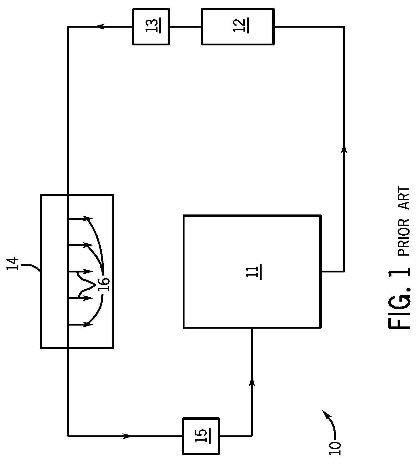
[0019]Referring to FIG. 1, a paint circulation system 10 includes a paint tank 11 containing a reservoir of liquid paint. A pump 12 is operable to supply paint from the paint tank 11, optionally through a paint filter 13, to a spray booth 14. The spray booth 14 typically includes one or more applicators 16. For example these may be spray nozzles manipulated by robot arms. Any unused paint flows past the spray booth and is returned to the paint tank 11 via a BPR 15.

[0020]In this set-up, the BPR 15 is employed to control the upstream pressure in the system at the desired level, typically 5 to 10 bar when the paint is in use. The BPR 15 typically includes a diaphragm, one side of which is acted upon by a coiled spring.

[0021]The pressure of paint entering the BPR 15 urges the diaphragm against the spring force to open up a passage for paint. Any reduction in paint pressure results in the diaphragm moving under the spring force, tending to close the passage. This acts as a restriction to...


PUM


Abstract

A paint circulating system is suitable for providing paint to applicators in a product finishing facility. The system includes a pump for pumping paint around the system and a back-pressure regulator (BPR), which substantially eliminates pressure fluctuations of paint in the system upstream of the BPR. A controller is provided for controlling the pump and the BPR to operate in one of a flow mode, wherein a required flow rate of paint around the system is maintained, and a pressure mode, wherein a pressure of paint between the pump and the BPR is maintained. The paint circulating method includes switching operation of the pump and the BPR between the flow mode and the pressure mode.

Description

[0001]The present invention relates to a paint circulating system and method, of a type suitable for use with automated spray finishing processes.BACKGROUND OF THE INVENTION[0002]Traditional paint spray systems, of the type employed in car manufacturing for example, usually consist of several separate paint lines, each providing a different coloured paint to a spray booth for distribution to a number of user points (e.g. spray applicators). In general, only one colour is sprayed or in use at any one time, so only one line is actively employed whilst the rest remain ready for use.[0003]When a system is not in use because the paint is not being sprayed, it is usual to maintain the spraying pressure and paint velocity in the paint line, by pumping paint from a paint tank around a circuit and back to the tank. This is done for two reasons: firstly, because the liquid paint must be kept moving, otherwise pigmentation may start to settle out in the paint lines; secondly, because the lines...

Claims


Application Information

Patent Timeline
Patent Type & Authority Patents(United States)
IPC IPC(8): F04B49/00
CPCB05B9/0423B05B12/085B05B12/14Y10T137/85954B05B12/08B05B9/04
Inventor SMITH, ALAN A.WOOD, NIGEL C.THOMAS, MICHAEL A.
Owner CARLISLE FLUID TECH INC
Why Eureka
Try Eureka