
Injection molding device and method

a molding cell and injection molding technology, applied in the field of injection molding devices and methods, can solve the problems of reducing the concentration of drugs, reducing the quality of silicone, and reducing the flow path of silicone, so as to reduce waste, improve quality and reproducibility, and reduce the effect of silicone flow path

Active Publication Date: 2014-05-13
JOHNSON & JOHNSON VISION CARE INC
View PDF19 Cites 2 Cited by
  • Summary
  • Abstract
  • Description
  • Claims
  • Application Information

AI Technical Summary

Benefits of technology

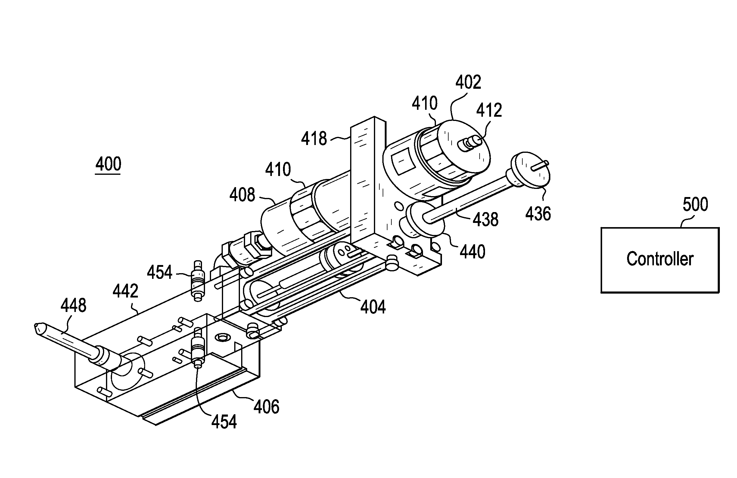
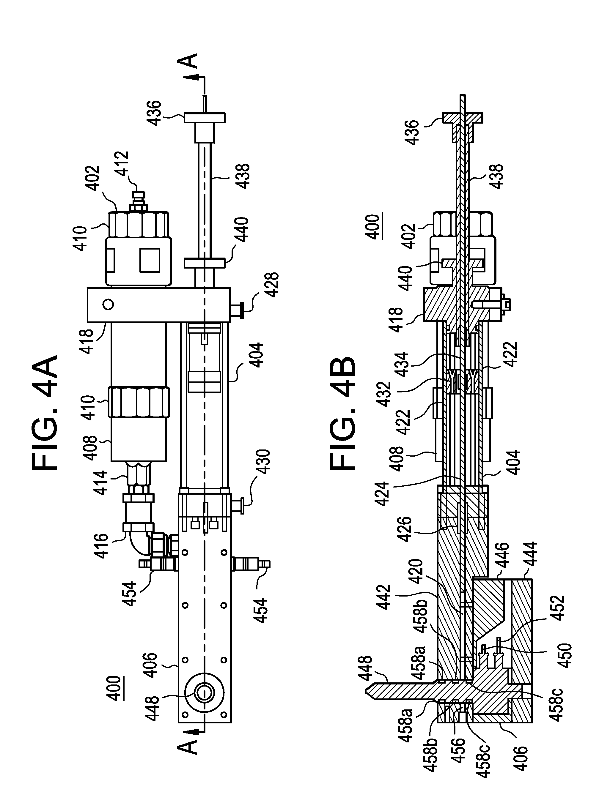
The present invention is a micro silicone mold mounted plunger system that improves quality and reproducibility while reducing waste. The system has a greatly reduced material flow channel diameter that holds constant up to the point of exiting the cold nozzle orifice, providing a stable pressure constant unlike a reciprocating screw system that begins with a larger diameter material channel and then reduces over the length of the flow path of the system. The micro sized, direct mold mounted silicone plunger injection unit has advantages such as small size, reduced material flow path volume, the elimination of pressure fluctuations, a significant reduction in the variation in the injection process, a reduction in material waste and costs because of the single cartridge system, and the whole unit mounts directly onto the mold thereby eliminating a machine injection unit.

Problems solved by technology

Rarely are drugs for the eye administered orally or by injection, either because they reach the eye in too low a concentration to have the desired pharmacological effect, or because their use is complicated by significant systemic side effects.
Eye drops, though effective, are unrefined and inefficient.
When an eye drop is instilled in the eye, it typically overfills the conjuctival sac, the pocket between the eye and the eyelids, causing a substantial portion of the drop to be lost due to overflow of the eyelid margin onto the cheek.
In addition, a substantial portion of the drop remaining on the ocular surface is washed away by tears into the tear drainage system, thereby diluting the concentration of the drug.
Not only is this share of the drug dose lost before it can cross the cornea, but this excess drug may be carried into the nose and throat where it is absorbed into the general circulation, sometimes leading to serious systemic side effects.
This tissue concentration then gradually decreases, such that by the time the next eye drop is due, the tissue concentration and the intended pharmacological effect may be too low.
Often, this poor compliance is due to an initial stinging or burning sensation caused by the eye drop.
Certainly, instilling eye drops in one's own eye can be difficult, in part because of the normal reflex to protect the eye.
Older patients may have additional problems instilling drops due to arthritis, unsteadiness, and decreased vision, and pediatric and psychiatric patient populations pose difficulties as well.
Devices so small are inherently more difficult to manufacture than larger devices.
More importantly, manufacturing small devices in a repeatable and reliable manner is even more difficult.

Method used


Image

  • Injection molding device and method
  • Injection molding device and method
  • Injection molding device and method

Examples


Embodiment Construction

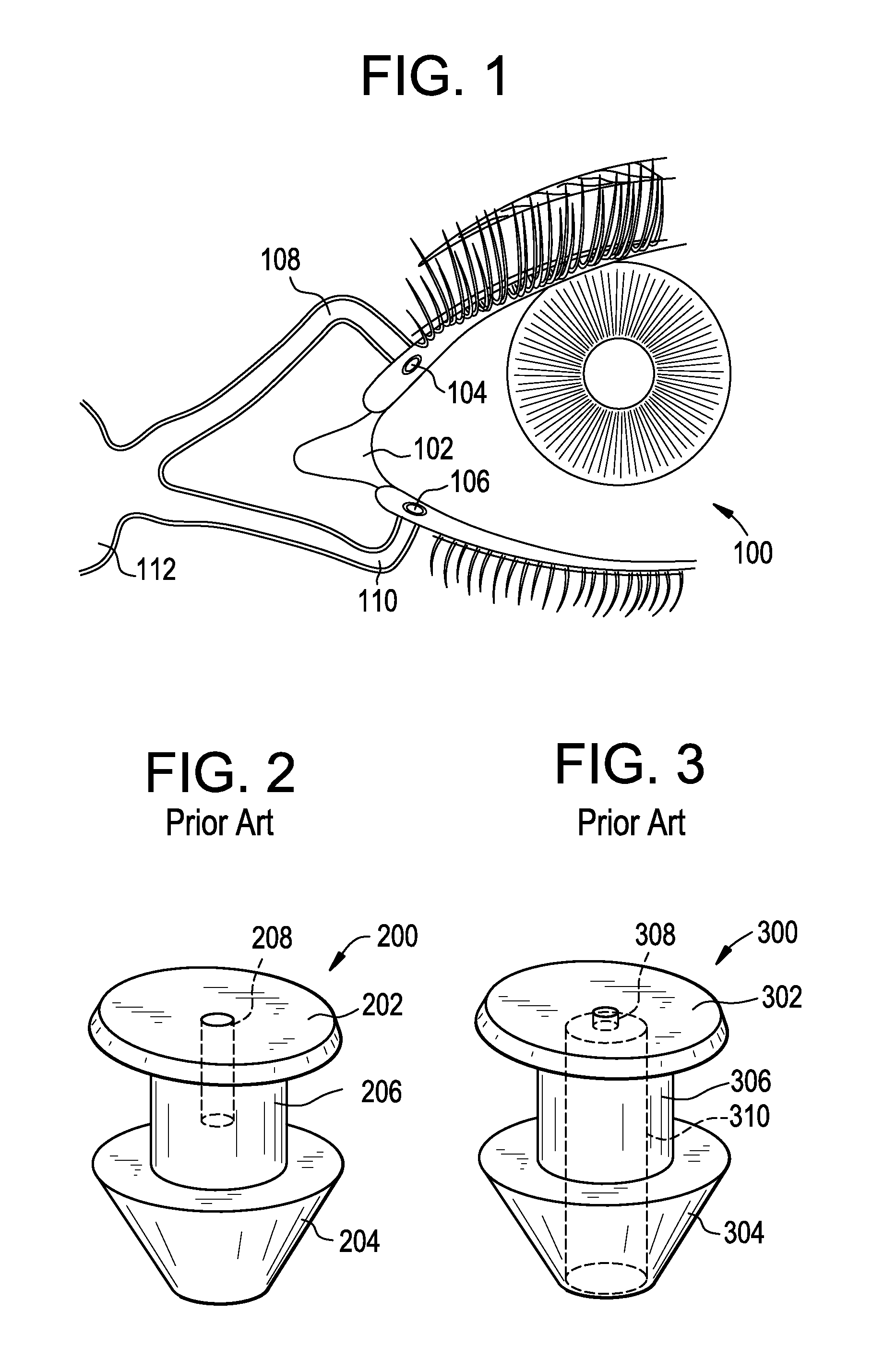
[0025]FIG. 1 illustrates the anatomy of the drainage system of a human eye 100. Tears are produced by the lacrimal gland, not illustrated, superior to the outer portion of each eye 100. Tears flow across the surface of the eye 100 to a shallow pool, termed the lacrimal lake 102, located where the upper and lower eyelids come together at their inner ends or nasal ends. From there, the tears drain through small openings in each of the eyelids, namely, the upper lacrimal punctum 104 and the lower lacrimal punctum 106. From the upper lacrimal punctum 104 and the lower lacrimal punctum 106, the tears pass into the upper lacrimal canaliculus 108 and lower lacrimal canaliculus 110, respectively, which are duct-like pathways leading to the lacrimal sac 112. The lacrimal sac 112 is the superior, expanded portion of the nasolacrimal duct, not illustrated, which drains tears into the nasal system. The upper lacrimal punctum 104 and associated canaliculus 108 typically only drain about ten perc...


PUM

PropertyMeasurementUnit
diameteraaaaaaaaaa
lengthaaaaaaaaaa
widthaaaaaaaaaa

Abstract

A micro silicone mold mounted plunger injection system comprises a silicone cartridge assembly, a micro plunger injection assembly and a cold deck nozzle assembly. In this system, these three components are interconnected directly such that it has a greatly reduced material flow path length and diameter. The system is capable of displacing an amount of material in a single shot substantially equal to the desired shot weight required to make a component.

Description

BACKGROUND OF THE INVENTION[0001]1. Field of the Invention[0002]The present invention relates to devices and methods for manufacturing medical devices, and more particularly to a fully automatic, miniature sized silicone molding cell that utilizes a novel silicone mold and plunger injection unit to produce a drug delivery device or portions thereof for use in the eye.[0003]2. Discussion of the Related Art[0004]The corner of each eye is called a canthus, with the nose side called the nasal canthus and the ear or temporal side called the temporal canthus. At the lower and upper eyelid margins of the nasal canthus are small openings called puncti or puncta. As used herein, both puncti and puncta shall be understood to be the plural form of punctum. Each punctum drains tears from the eyes. A punctal plug or occluder is an ophthalmic device for insertion into a punctum of an eye in order to treat one or more disease states. Typically, a punctal plug is positioned to block tear drainage t...

Claims


Application Information

Patent Timeline
Patent Type & Authority Patents(United States)
IPC IPC(8): B29C45/02
CPCB29C45/02B29L2031/756B29C2045/0094B29L2031/753B29K2083/005A61K9/0051A61F9/00772B29C45/03B29C45/18
Inventor MCATEER, VINCENT GKIPE, GEORGE B.LUST, VICTORPARNELL, SR., PHILLIP KING
Owner JOHNSON & JOHNSON VISION CARE INC
Learn More