
Audio magnetic connection and indexing device
a technology of indexing device and audio magnetic connection, which is applied in the direction of coupling device connection, transducer casing/cabinet/support, electrical transducer, etc., can solve the problems of inaccurate positioning and indexing, and the difficulty of comparing products to one another, so as to reduce the use of external fasteners.
- Summary
- Abstract
- Description
- Claims
- Application Information
AI Technical Summary
Benefits of technology
Problems solved by technology
Method used
Image

Examples
Embodiment Construction
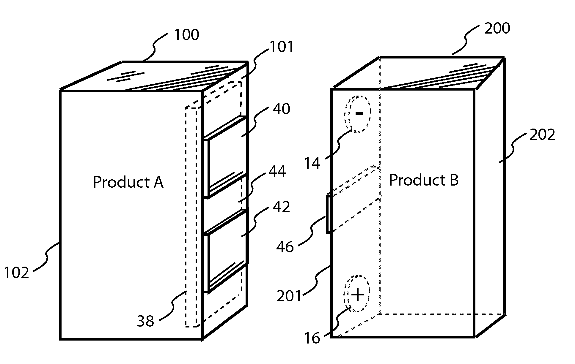
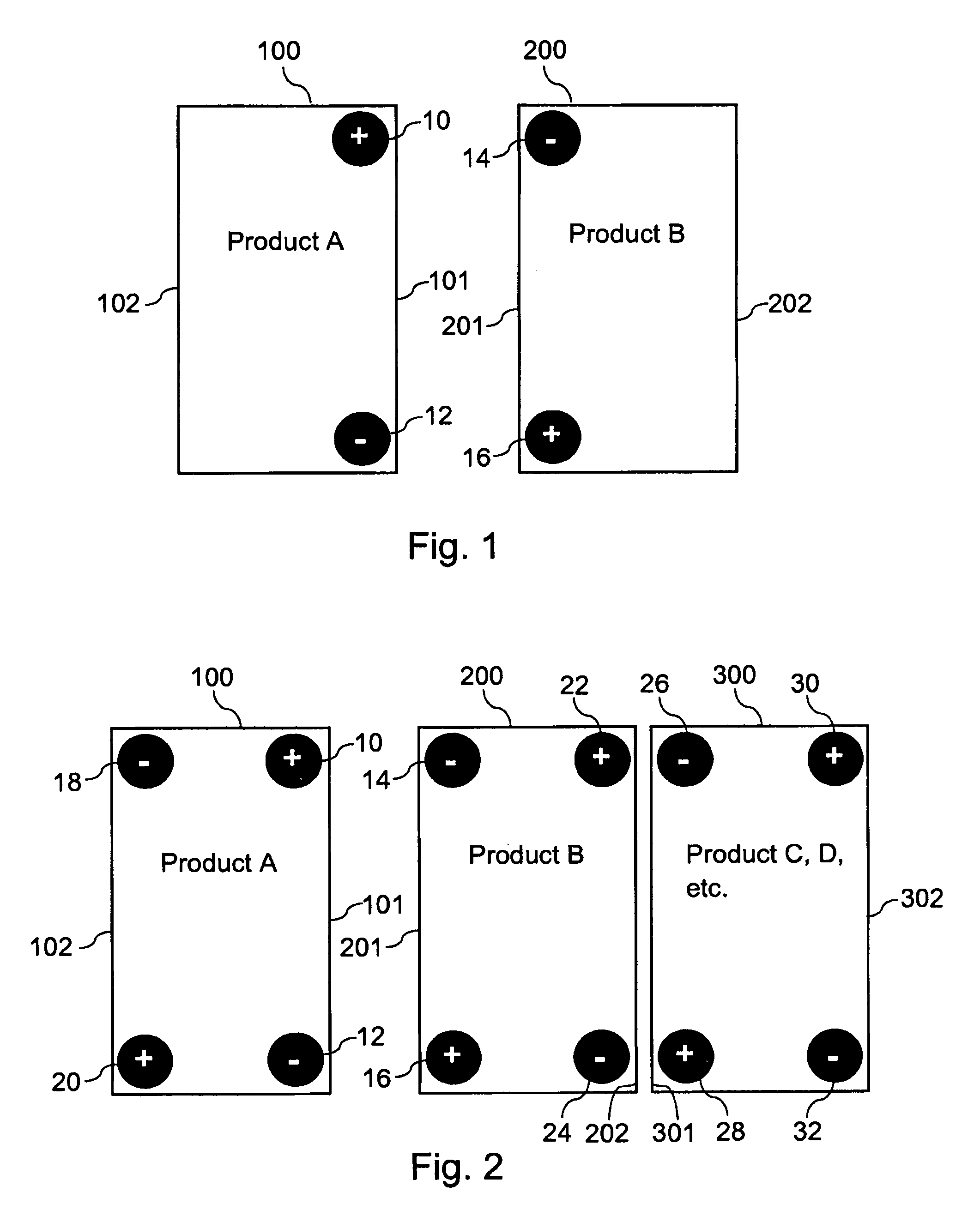
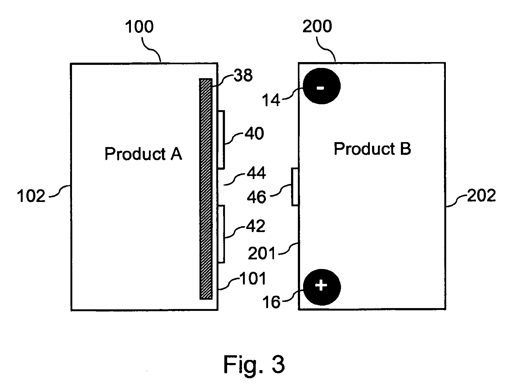
[0014]Referring now to the drawings in detail wherein like numerals indicate like elements throughout the several views, one sees that FIG. 1 is a schematic of the first embodiment of the present invention. More specifically, FIG. 1 shows the respective abutting ends 101, 201 of the exterior cases of electronic components 100 and 200 which are to be positioned against each other. Electronic components 100, 200 may be audio components, such as, but not limited to, power amplifiers, pre-amplifiers, integrated amplifiers, radio tuners, CD or DVD players or other audio sources or sound processors. Furthermore, electronic components 100, 200 may be audio / visual recording devices or scientific instruments, but are not limited thereto.
[0015]Component 100 includes magnet 10 outwardly presenting a positive pole on an upper portion of end 101 of component 100 and further includes magnet 12 outwardly presenting a negative pole on a lower portion of end 101 of component 100. Likewise, component...
PUM
 Abstract
Description
Claims
Application Information