
Two-level branch prediction apparatus

a branch prediction and apparatus technology, applied in the direction of instruments, specific program execution arrangements, program control, etc., can solve the problem of quite limited number of separate entries that can be provided in each cache, and achieve the effect of reducing aliasing issues

Active Publication Date: 2010-11-09
ARM LTD
View PDF12 Cites 13 Cited by
  • Summary
  • Abstract
  • Description
  • Claims
  • Application Information

AI Technical Summary

Benefits of technology

[0025]The inventor of the present invention realised that this second type of aliasing becomes a more and more significant factor as the resources available for the prediction logic are reduced, and accordingly the cache sizes are reduced.
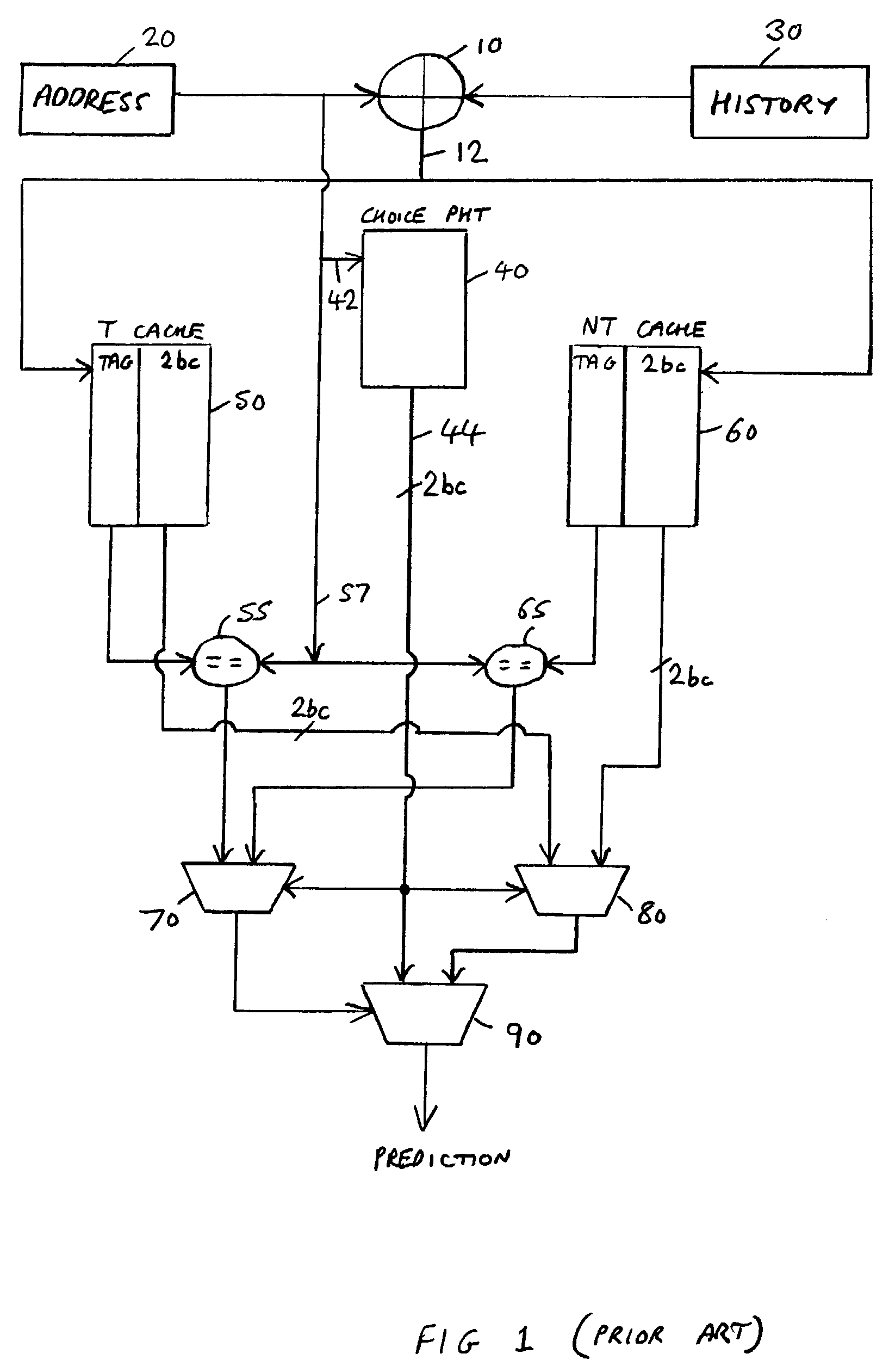
[0028]This consolidation of the second level look-up resource into a single second branch bias storage improves flexibility since any of the entries can be used for an exception to either a “not taken” bias or a “taken” bias. In addition, since for a given storage budget there are now more individual entries to be indexed (of the order of twice as many as would be the case if two separate caches were provided as per the YAGS technique approach), then a finer granularity of indexes can be generated by the index generation logic, thereby reducing the likelihood of occurrence of the earlier described second type of aliasing. In addition, it should be noted that the use of the approach of the present invention enables a significant reduction in the complexity of the selection logic since there is now only a single second branch bias storage outputting an entry, rather than two different T and NT caches outputting entries.
[0029]In addition, it has surprisingly been found that, at least in implementations of the type mentioned earlier where there are reduced resources available for the prediction logic, any increase in the first type of destructive aliasing (i.e. the type of aliasing which the YAGS approach was aiming to reduce) resulting from the approach of the present invention is not significant, and is far outweighed by the benefits realised in reducing the second type of aliasing and in increasing flexibility.
[0033]It will be appreciated that the single second branch bias storage can take a variety of forms. However, in one embodiment, the single second branch bias storage is a set associative storage, wherein the index identifies multiple corresponding entries in the single second branch bias storage, the selection logic being operable to determine whether any of the TAG values output from the corresponding entries correspond to the comparison TAG value, and in the event of such correspondence with the TAG value of one of said corresponding entries, to select the replacement branch bias value for that one corresponding entry as the branch bias generated by the branch prediction logic. Use of a set associative storage further reduces aliasing issues, by enabling more than one entry to be provided for any particular index generated by the index generation logic.
[0034]In one embodiment, the multiple entries provided for a particular index will not have the same TAG value and hence the selection logic will not need to provide for situations where more than one of the TAG values output from the single second branch bias storage match the comparison TAG value. In such situations, the selection logic may include a simple priority encoder to determine which replacement bias value to output dependent on which, if any, of the TAG values output from the single second branch bias storage match the comparison TAG value.

Problems solved by technology

In particular, if the size available for the table and caches of the YAGS technique is relatively small, then the number of separate entries that can be provided in each cache becomes quite limited.

Method used


Image

  • Two-level branch prediction apparatus
  • Two-level branch prediction apparatus
  • Two-level branch prediction apparatus

Examples


Embodiment Construction

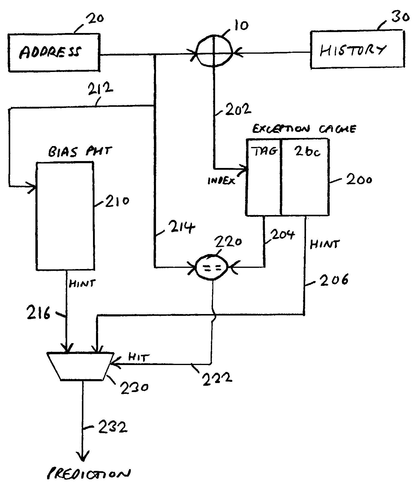
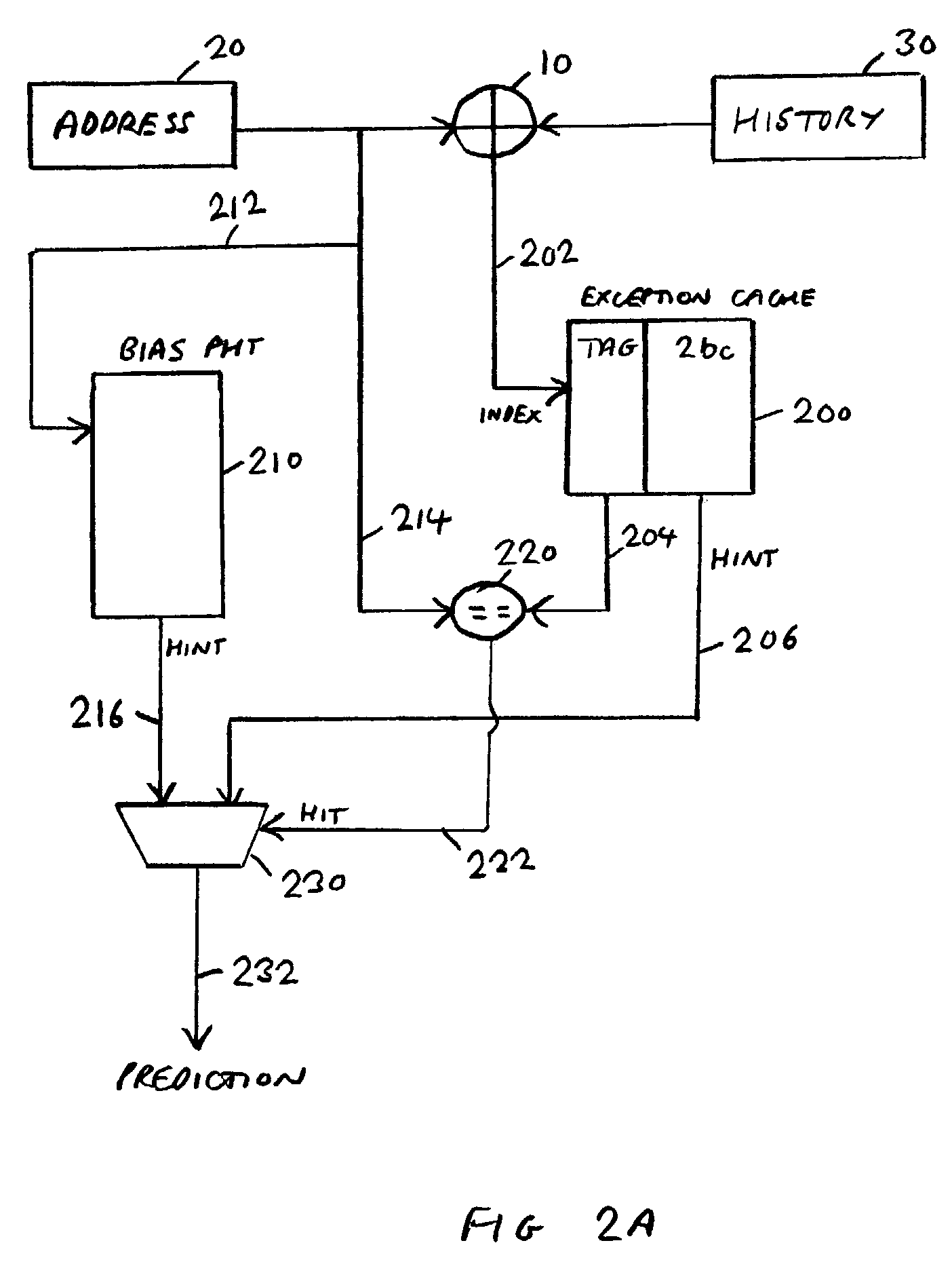
[0058]FIG. 2A is a block diagram illustrating a branch prediction scheme in accordance with one embodiment of the present invention. In a similar manner to that described earlier with reference to the YAGS prediction scheme, index generation logic 10 is operable to receive both an address 20 for an instruction to be evaluated, and history data from a history register 30 identifying for a number of preceding branch instructions whether those branch instructions were taken or not taken. The index generation logic 10 is operable to generate, from a logical combination of the history data and the branch instruction's address, an index output over path 202 to a single exception cache 200. In alternative embodiments, it will be appreciated that the index generation logic may be arranged to generate an index based solely on the history data.

[0059]Additionally, a first portion of the instruction address 20 is routed over path 212 to act as an index into a bias PHT 210. The bias PHT 210 is a...


PUM


Abstract

A two-level branch prediction apparatus includes branch bias logic for predicting whether a branch instruction will result in a branch being taken. Upon receipt of a first address portion of a branch instruction's address, a first store outputs a corresponding first branch bias value. A history store stores history data identifying an actual branch outcome for preceding branch instructions. A second store stores multiple entries, each entry including a replacement branch bias value and a TAG value. An index derived from the history data causes the second store to output a corresponding entry. The first branch bias value is selected unless the TAG value corresponds to a comparison TAG value derived from a second address portion of the branch instruction's address, in which event, the replacement branch bias value is selected.

Description

BACKGROUND OF THE INVENTION[0001]1. Field of the Invention[0002]The present invention relates to techniques for performing branch prediction in a data processing apparatus.[0003]2. Description of the Prior Art[0004]A data processing apparatus will typically include one or more execution units which are operable to execute a sequence of instructions. A prefetch unit will typically be provided for prefetching instructions from a memory, for example an instruction cache, prior to those instructions being passed to the required execution unit. The prefetch unit will typically include an incrementer for incrementing a current program counter (PC) value to produce an instruction address for a next instruction or set of instructions to be prefetched. However, when a branch instruction is encountered within the instruction flow, this may cause a discontinuous jump in the PC value if the branch specified by that branch instruction is taken. As an example of such a branch instruction, a branc...

Claims


Application Information

Patent Timeline
Patent Type & Authority Patents(United States)
IPC IPC(8): G06F9/00G06F9/38
CPCG06F9/3848
Inventor BILES, STUART DAVID
Owner ARM LTD
Learn More