Automatic cable car facility

a technology of automatic cable car and cable car, which is applied in the direction of transportation and packaging, railway components, rope railways, etc., can solve the problems of passengers' reaction, detriment of the efficiency of installation, and specific delay of the only vehicl

Active Publication Date: 2010-11-16
ROPETRANS AG
View PDF36 Cites 9 Cited by
  • Summary
  • Abstract
  • Description
  • Claims
  • Application Information

AI Technical Summary

Benefits of technology

[0006]The object of the present invention consists in producing an automatic installation for the transport of vehicles by cable, allowing vehicles released in stations to exceed the allocated time for drop-off and / or pick-up in stations, without affecting the smoothness of operation of the endless stream of the other vehicles that are in the line and in stations.
[0010]Each station is also furnished with at least one compensation position in which there is permanently an empty reserve vehicle capable of filling an empty space left by a vehicle delayed and stopped at the pick-up / drop-off position. If, for any reason, a vehicle that has to be reinserted into the path is not ready to depart, it remains in its position thereby creating a gap in the path, a gap that will be immediately filled by one of the available reserve vehicles, thereby reconstituting the timing of the installation.

Problems solved by technology

Exceeding a predetermined drop-off and / or pick-up time results in a delay specific to the only vehicle concerned.
The problem is different when such a delay affects a vehicle forming part of an endless stream of vehicles which, if no particular arrangement has been provided, is forced to stop in order to wait for the delayed vehicle.
All the vehicles in the line are then stopped to the detriment of the efficiency of the installation and this is likely to cause a reaction of the passengers when it involves passenger transport.

Method used


Image

  • Automatic cable car facility
  • Automatic cable car facility
  • Automatic cable car facility

Examples


Embodiment Construction

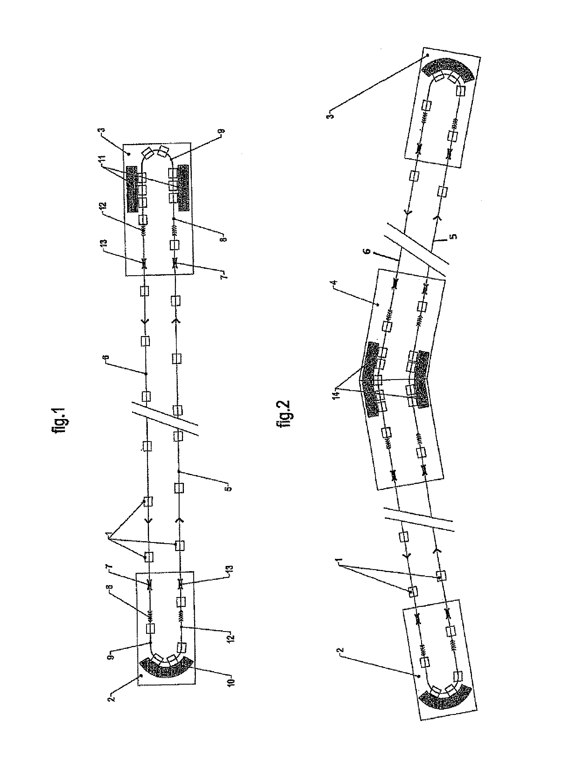
[0026]With reference to FIGS. 1 and 2, a plurality of vehicles 1 move on a track 5 in a closed loop from a first station 2 to a second station 3, if necessary with an intermediate station 4 (FIG. 2). The vehicles 1 return in the reverse direction over another parallel track 6 thanks to one or more carrier or puller cable(s) in the case of a cable car, or any other track and means of traction for other types of conveyors.

[0027]Between the various stations 2, 3, 4 of the loop, the vehicles 1 move at great speed, for example at several meters per second, and are distributed evenly, with reduced time intervals of the order of a few seconds.

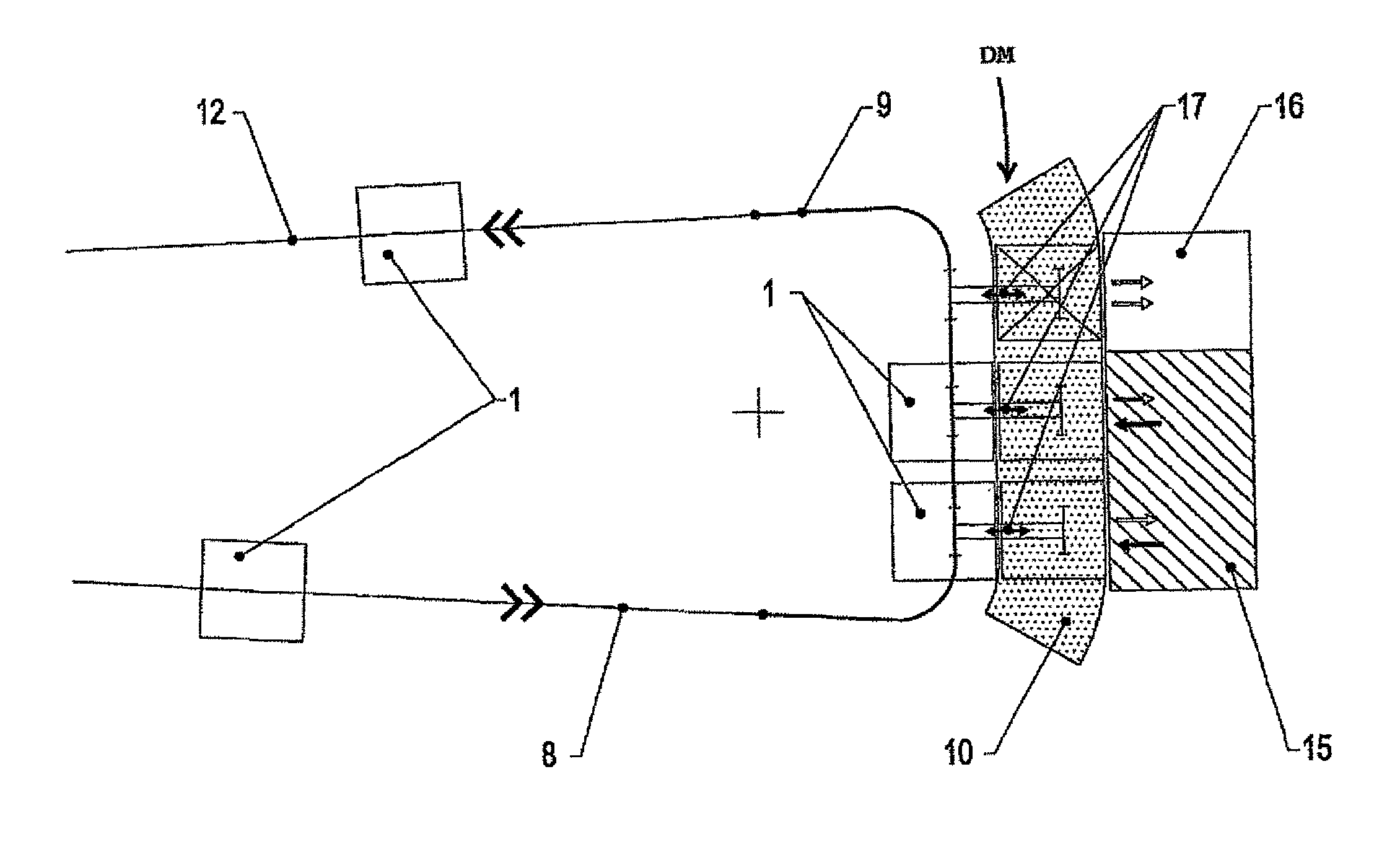
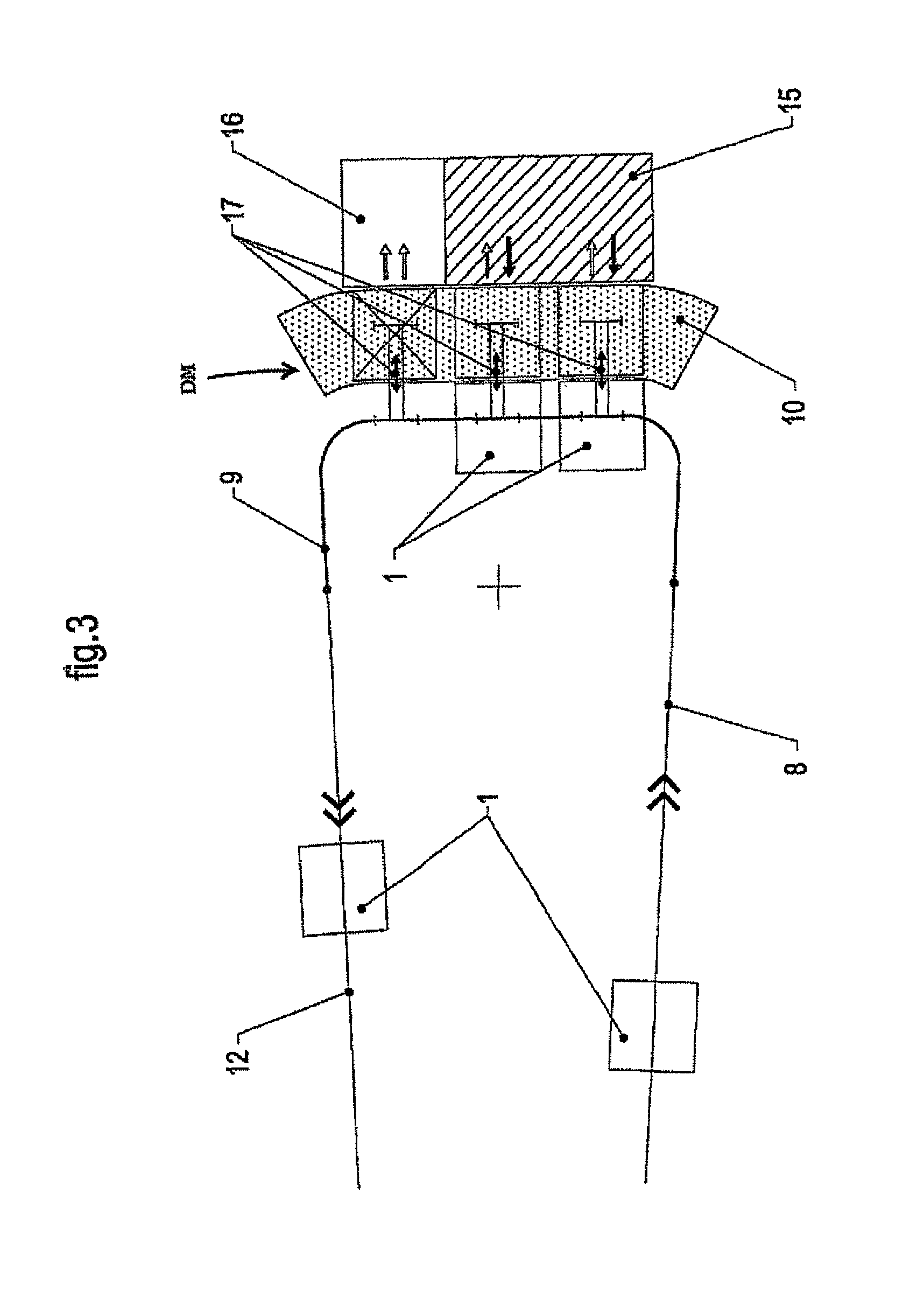
[0028]On entering one of the end stations 2, 3, the vehicles 1 are released from the cables at the releasing zone 7, and then are decelerated over a certain length in the deceleration zone 8. They then travel at slow speed along a released circuit furnished with a contour 9 turning them round, and pass, depending on the type of stations, in front of d...


PUM


Abstract

Automatic cable transport facility along a closed loop line, including vehicles that can be disengaged at a set rate in stations after moving along a disengaged circuit where they are driven at low speed along disembarkation and embarkation platforms. Each station includes an automatic control mechanism able to extract the vehicles from the slow progression in the disengaged circuit, and transfer them to a disembarkation / embarkation point which is assigned to them in order of arrival, the previous vehicle having previously been reintegrated into the slow progression line in the place of the vehicle extracted in accordance with a preset program. A compensation point includes a permanently available spare empty vehicle which can be used to fill an empty space left by a vehicle that has been delayed and stopped at the disembarkation / embarkation point.

Description

TECHNICAL FIELD OF THE INVENTION[0001]The present invention relates to an automatic cable transport installation along a closed loop line, comprising releasable vehicles timed in stations or in an intermediate station after passing over a released circuit where they are driven at slow speed along drop-off and pick-up platforms, the vehicles then being reaccelerated and recoupled to the cable at the exit of the station in order to constitute an endless stream of vehicles.PRIOR ART[0002]Many automatic transport means are known, that is to say that operate without the need for the permanent presence of supervision personnel at the drop-off and pick-up of the passengers (or the materials).[0003]The most common of them is the elevator having a virtually total safety and with a minimum of operating problems.[0004]There also exist many people transporters and automatic funicular railways furnished with an operation that is back-and-forth, back-or-forth, or that has a considerable gap betwe...

Claims


Application Information

Patent Timeline
Patent Type & Authority Patents(United States)
IPC IPC(8): B61B12/00
CPCB61B10/02B61B12/022
Inventor RICHARD, JEROME
Owner ROPETRANS AG
Why Eureka
Try Eureka