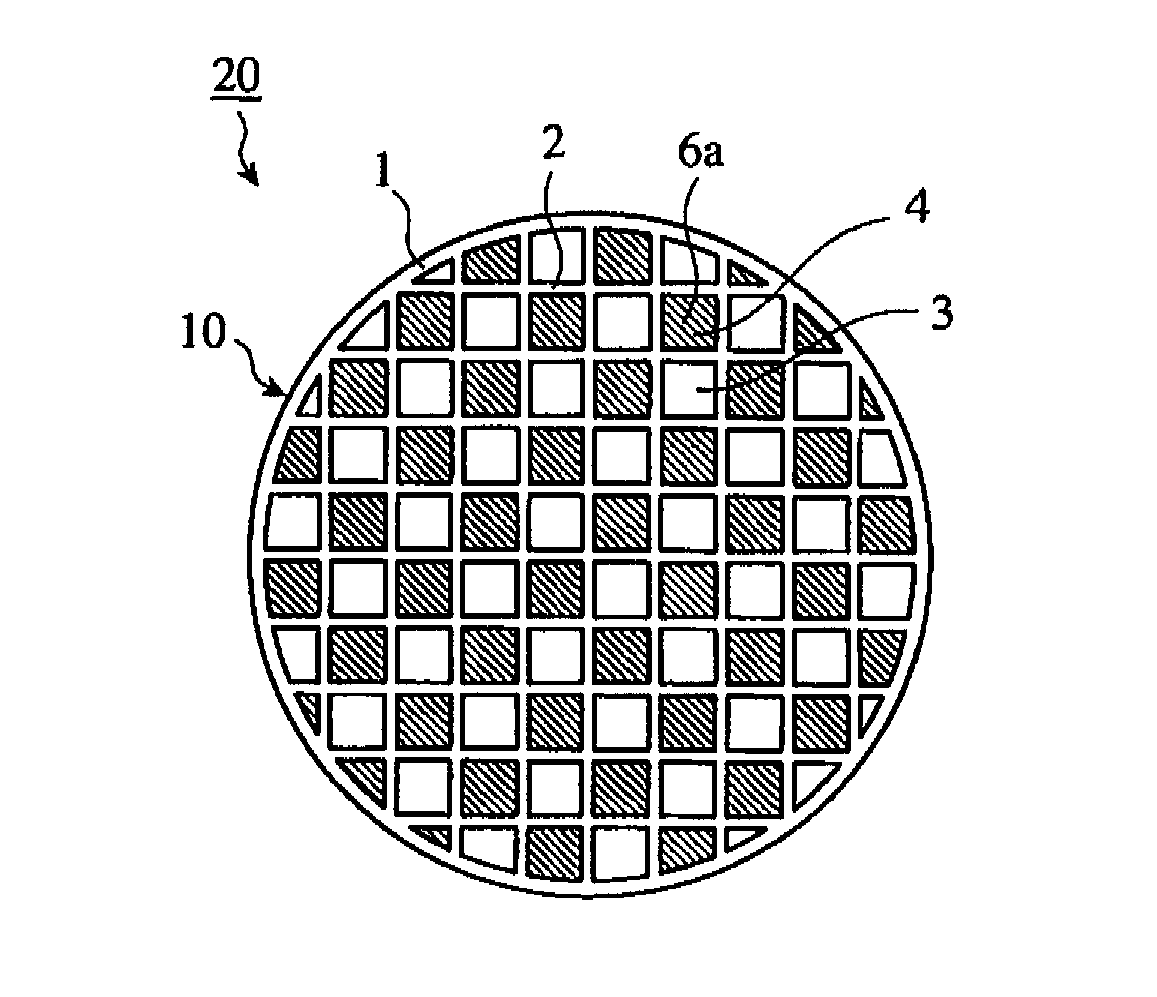
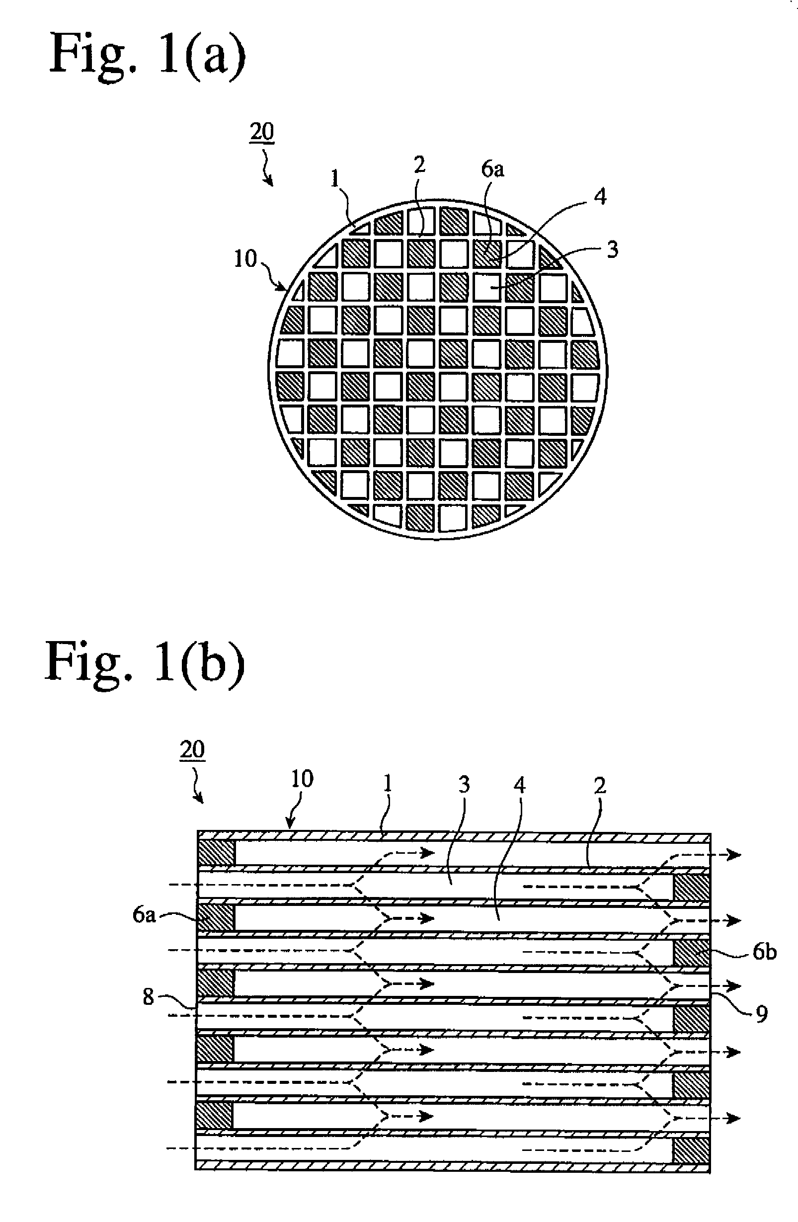
Ceramic honeycomb structure and method for producing ceramic honeycomb structure
a honeycomb and ceramic technology, applied in the field of ceramic honeycomb structure, can solve the problems of increased pressure loss, large heating energy consumption, adverse effects on humans and the environment, etc., and achieve the effect of less pressure loss increase and long capture tim
- Summary
- Abstract
- Description
- Claims
- Application Information
AI Technical Summary
Benefits of technology
Problems solved by technology
Method used
Image

Examples
example 1
[0052]The powders of kaolin, talc, silica A (fused silica), alumina and aluminum hydroxide shown in Tables 1 and 2 were weighed to the formulation A shown in Table 3 to obtain a cordierite-forming material powder. Added to 100 parts by mass of this cordierite-forming material powder were 6 parts by mass of a foamed resin having an average particle size of 60 μm as a pore-forming material, and methylcellulose and hydroxypropylmethylcellulose as a binder. After fully dry-mixed, water was added, and blending was conducted to prepare a moldable ceramic material. The specific surface area of each powder was measured by a BET method, and the average particle size of each powder was measured by a laser diffraction method. The aspect ratio was determined by measuring the largest diameters and the smallest diameters of arbitrary 10 particles on a SEM photograph, and averaging (largest diameter) / (smallest diameter) ratios. This moldable material was extrusion-molded, cut and dried to obtain a...
examples 2-5
[0057]Ceramic honeycomb filters of Examples 2, 3, 4 and 5 were produced in the same manner as in Example 1 except for using as a pore-forming material a foamed resin having an average particle size of 60 μm in an amount of 8 parts by mass, 10 parts by mass, 12 parts by mass and 14 parts by mass, respectively.
examples 6 and 7
[0058]Ceramic honeycomb filters of Examples 6 and 7 were produced in the same manner as in Example 3 except for changing the formulation of the ceramic material powder to the formulations B and C shown in Table 3.
PUM
| Property | Measurement | Unit |
|---|---|---|
| particle size | aaaaa | aaaaa |
| BET specific surface area | aaaaa | aaaaa |
| pore diameter | aaaaa | aaaaa |
Abstract
Description
Claims
Application Information
 - R&D Engineer
- R&D Manager
- IP Professional
- Industry Leading Data Capabilities
- Powerful AI technology
- Patent DNA Extraction
Browse by: Latest US Patents, China's latest patents, Technical Efficacy Thesaurus, Application Domain, Technology Topic.
© 2024 PatSnap. All rights reserved.Legal|Privacy policy|Modern Slavery Act Transparency Statement|Sitemap