Synchronization module

a technology of synchronization module and synchronization frequency, applied in the field of synchronization module, can solve the problems of increasing the cost of hardware implementation several times, and achieve the effect of increasing the cost and synchronizing accuracy

Active Publication Date: 2010-11-16
UNIFY GMBH & CO KG
View PDF10 Cites 16 Cited by
  • Summary
  • Abstract
  • Description
  • Claims
  • Application Information

AI Technical Summary

Benefits of technology

[0007]While it is true that higher synchronizing accuracies can basically be achieved using a PTP protocol implemented by hardware means, said kind of hardware implementation also increases the costs several times.

Problems solved by technology

While it is true that higher synchronizing accuracies can basically be achieved using a PTP protocol implemented by hardware means, said kind of hardware implementation also increases the costs several times.

Method used


Image

  • Synchronization module
  • Synchronization module
  • Synchronization module

Examples


Embodiment Construction

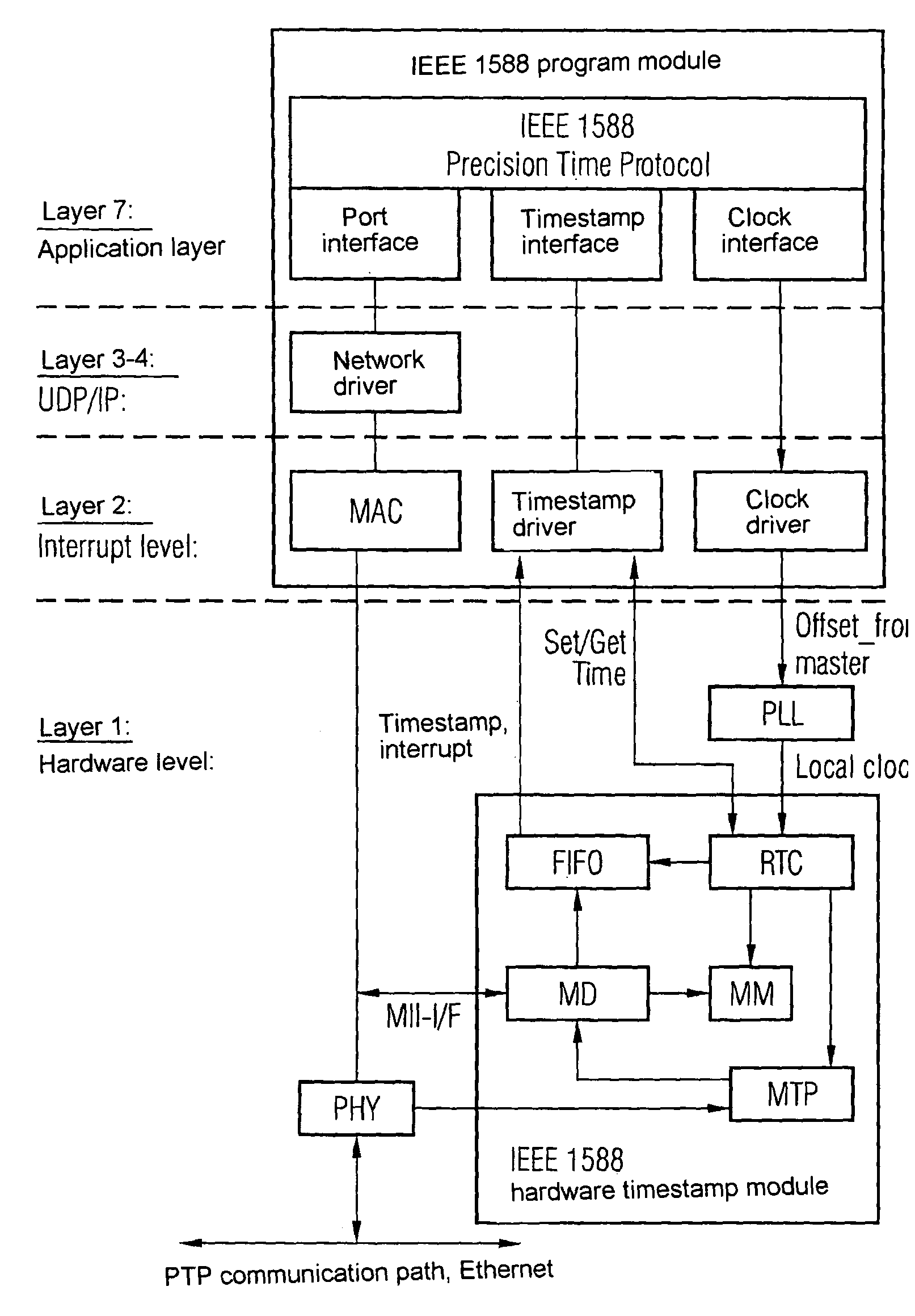
[0014]FIG. 1 is a chart from Section 6.2.4 of the known IEEE 1588™ 2002 standard document illustrating different timestamp points and their latencies. A message timestamp point illustrated there is an identifying feature of synchronization messages such as the PTP protocol's Sync and Delay_Req messages shown in FIG. 1. The message timestamp point can be identified if the relevant message passes through the clock timestamp point according to the PTP protocol. FIG. 1 shows a typical Sync or Delay_Req message that traverses the PTP protocol stack for inbound data packets along the arrowed dashed line. The message timestamp point represented in FIG. 1 by the first “11” bit pattern of the message after a series of leading “10” bit patterns passes through the clock timestamp point after an inbound_latency period after exiting the physical transmission medium. The above explanations are analogously applicable also to the timestamps and latencies of outbound synchronization messages.

[0015]F...


PUM


Abstract

A synchronization module for providing synchronization messages to be sent with a time stamp in accordance with the PTP protocol of standard IEEE 1588 is provided. The synchronization module comprises a program module for generating a synchronization message to be sent and for providing the synchronization message with a first time stamp, and a hardware-implemented time stamp module which receives synchronization messages from the program module and forwards them in accordance with the PTP protocol. The time stamp module comprises a real time clock, a message detector for recognizing a synchronization message by its difference in relation to other messages and a message manipulator for overwriting the first time stamp in a synchronization message recognized by the message detector with a second time stamp actually retrieved from the real time clock.

Description

CROSS REFERENCE TO RELATED APPLICATIONS[0001]This application is the US National Stage of International Application No. PCT / EP2005 / 056193 filed Nov. 24, 2005 and claims the benefit thereof. The International Application claims the benefits of German application No. 102004061127.0 DE filed Dec. 16, 2004, both of the applications are incorporated by reference herein in their entirety.FIELD OF INVENTION[0002]The present invention relates to a synchronization module.[0003]Stringent requirements are placed on the time synchronicity of components employed in distributed communication or data-processing systems. The clock generators of said components are frequently synchronized with each other via an asynchronous network through an exchange of data packets provided with time stamps, or with a reference clock generator accessible via the asynchronous network.BACKGROUND OF THE INVENTION[0004]What is termed the PTP protocol (PTP: Precision Time Protocol), which is defined in the IEEE 1588 st...

Claims


Application Information

Patent Timeline
Patent Type & Authority Patents(United States)
IPC IPC(8): H04J3/06
CPCH04J3/0697H04J3/0658
Inventor ERICH, ARMINSCHULER, STEPHAN
Owner UNIFY GMBH & CO KG
Why Eureka
Try Eureka