
Composite shower head

a shower head and shower head technology, applied in dental surgery, lighting and heating equipment, combustion types, etc., to achieve the effect of convenient use and simplified shower si

Inactive Publication Date: 2010-11-23
XIAMEN SOLEX HIGH TECH IND CO LTD
View PDF3 Cites 20 Cited by
  • Summary
  • Abstract
  • Description
  • Claims
  • Application Information

AI Technical Summary

Benefits of technology

[0005]It is therefore a main object of the present invention to provide a composite shower head combining a shower head and a hand-hold shower head into one composite body, which can be took apart only in necessary time.
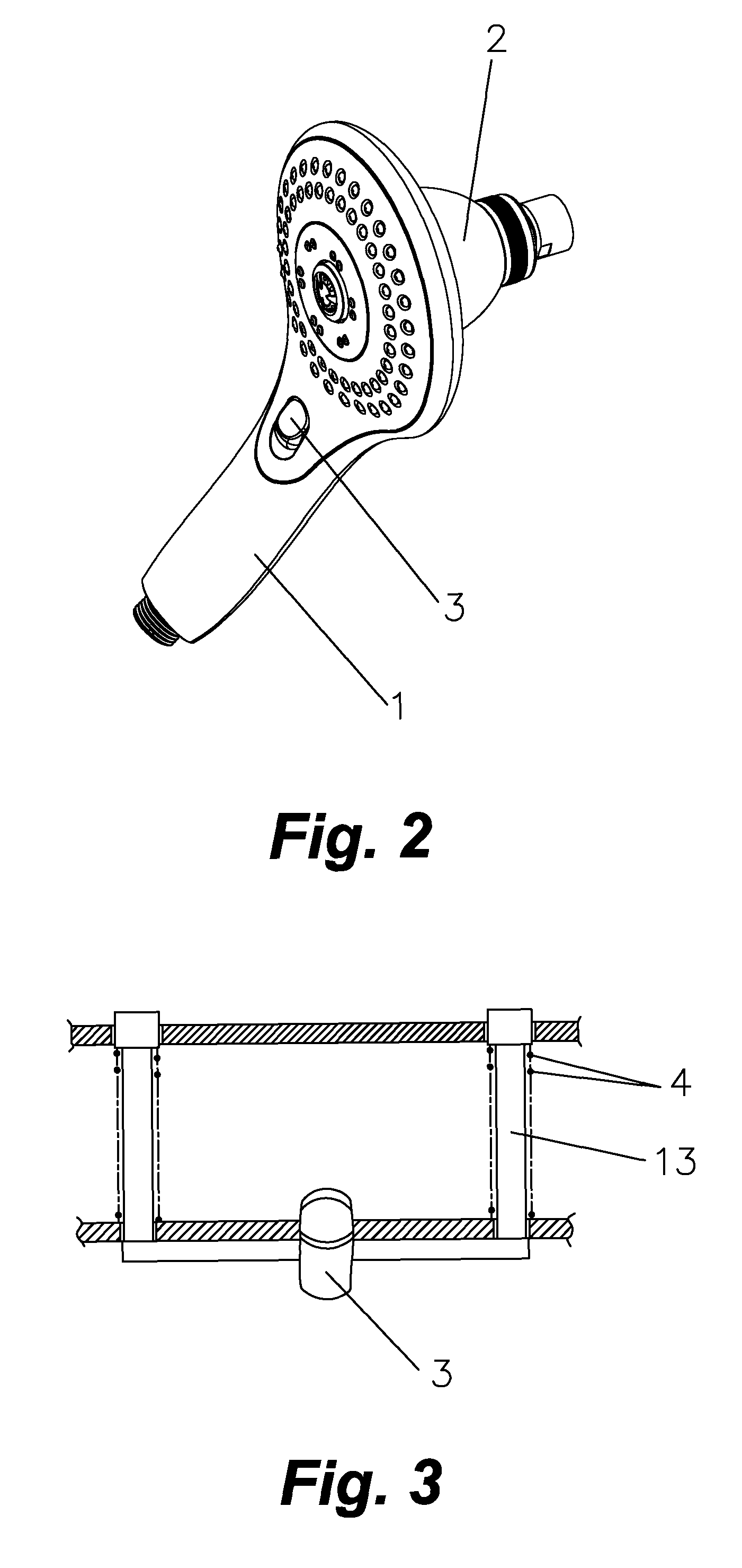
[0007]Said locking device includes one or more locking studs built on the inside of the hand-hold shower head and a coordinated catching groove built on the outside wall of the fixed shower head, in which said locking studs is controlled by a sliding button built upon the side wall of the retaining pass to stretch out from the hand-hold shower head to lock into the catching groove of the fixed shower head or to draw back from the catching groove to release the fixed shower head, and springs built upon the inside of the hand-hold shower head for keeping the locking studs extending out into the inside of the retaining pass always without any extra force drawing back.
[0011]As utilizing above-mentioned structure, in practice, because the hand-hold shower head is located on the fixed shower head directly to form an integrated top spraying state, and the hand-hold shower head does not need to be attached with shower stationary rest built on the wall; when the user tends to use the hand-hold shower head, just need to take apart the hand-hold shower head from the fixed shower head to hold to any where at will. In this way, the composite shower head combining the fixed shower head and the hand-hold shower head together into one assembled body simplifies the shower site, and facilitates to use, meanwhile meets to economic style of modern people.

Problems solved by technology

But, when the hand-hold shower head is not used, it must be located in a place, so a shower stationary rest should be fixed on the wall at proper position, or a shower adjustment rail, or the fixed shower head, separating with the fixed shower head, such like in the shower site, multiple shower heads are presented affecting looking view, and not meeting to economic style of modern people.

Method used


Image

  • Composite shower head
  • Composite shower head
  • Composite shower head

Examples


Embodiment Construction

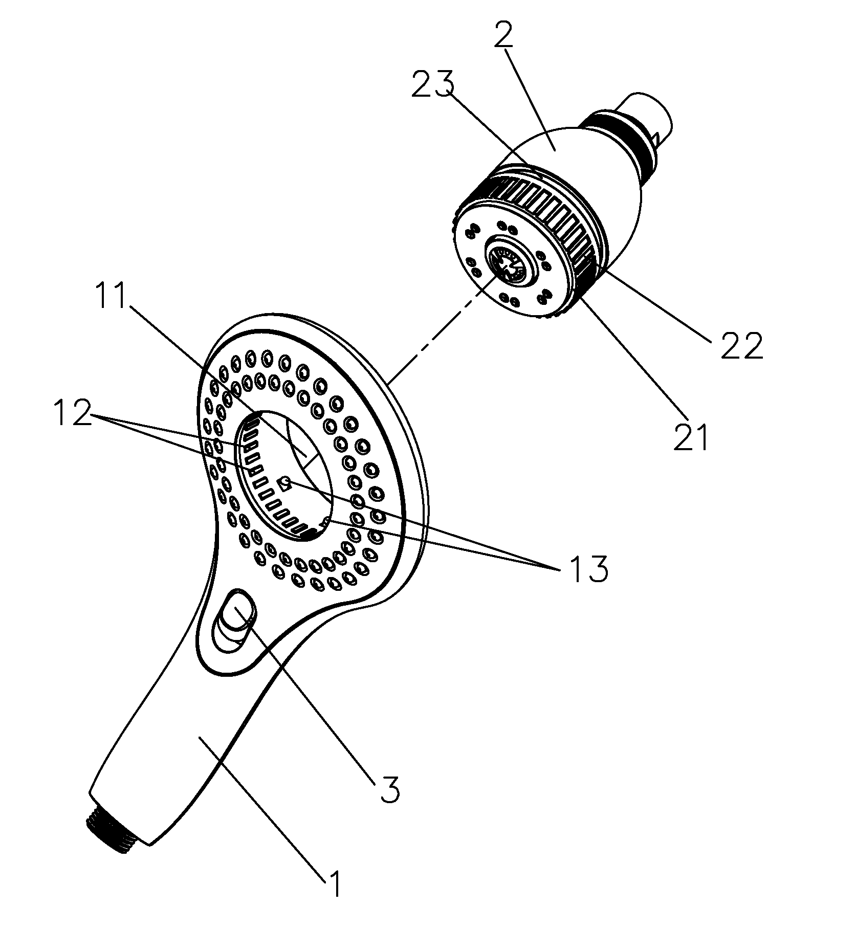
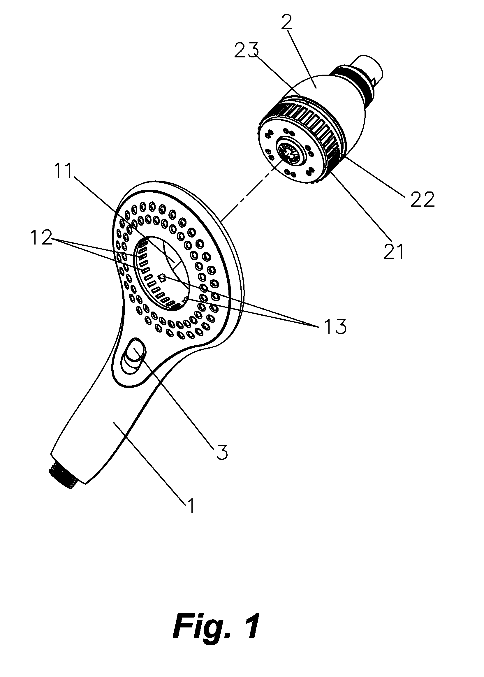
[0015]Referring to FIG. 1 and FIG. 2, a composite shower head discovered by the present invention is typically comprised of a hand-hold shower head 1, and a fixed shower head 2.

[0016]Wherein, said hand-hold shower head 1 has a retaining pass 11 coordinating to the fixed shower head 2, and proper number of gearing projections 12 built on the inside wall along the edge.

[0017]Said fixed shower head 2 can be held in the inside of the retaining pass 11 of the hand-hold shower head 1, and has an adjusting ring 21 built on the front panel for adjusting the spraying styles according to the necessary, there are a number of gearing slots 22 corresponding to the gearing projections 12 for gearing together and locating.

[0018]On the other head, a locking device can be built on between said hand-hold shower head 1 and the fixed shower head 2 (referring to FIG. 3), said locking device includes one or more locking studs 13 built on the inside of the hand-hold shower head 1 and one or more coordinat...


PUM


Abstract

The present invention provides a composite shower head typically comprised of a hand-hold shower head and a fixed shower head, wherein said hand-hold shower head has a retaining pass corresponding to the fixed shower head; said fixed shower head can be held in the retaining pass of said hand-hold shower head; a locking device is built on for locking the hand-hold shower head with the fixed shower head together. The composite shower head combining the fixed shower head and the hand-hold shower head together into one assembled body simplifies the shower site, and facilitates to use, meanwhile meets to economic style of modern people.

Description

BACKGROUND OF THE INVENTION[0001]1. Field of the Invention[0002]The present invention relates to bathroom appliances, and more particularly to a composite shower head.[0003]2. Description of Prior Art[0004]In accordance with the conventional technology, most of the shower heads are fixed above the head of user, meanwhile a hand-hold shower head is equipped for moving at will, in this way, the user can be convenient to select showing way. But, when the hand-hold shower head is not used, it must be located in a place, so a shower stationary rest should be fixed on the wall at proper position, or a shower adjustment rail, or the fixed shower head, separating with the fixed shower head, such like in the shower site, multiple shower heads are presented affecting looking view, and not meeting to economic style of modern people.OBJECTS AND SUMMARY OF THE INVENTION[0005]It is therefore a main object of the present invention to provide a composite shower head combining a shower head and a ha...

Claims


Application Information

Patent Timeline
Patent Type & Authority Patents(United States)
IPC IPC(8): B05B15/06B05B17/00B05B1/00A62C31/02B05B1/14
CPCB05B1/185B05B15/06B05B15/065E03C1/0409B05B15/60B05B15/65
Inventor ZHOU, HUASONG
Owner XIAMEN SOLEX HIGH TECH IND CO LTD
Learn More