Bicycle rear wheel suspension system

a rear wheel and suspension system technology, applied in the field of bicycle rear wheel suspension system, can solve the problems of affecting bicycle performance affecting bicycle performance as well as stopping ability, etc., and achieve the effect of reducing the size of the contact patch of the rear wheel

Inactive Publication Date: 2010-11-23
TREK BICYCLE CORPORATION
View PDF117 Cites 113 Cited by
  • Summary
  • Abstract
  • Description
  • Claims
  • Application Information

AI Technical Summary

Benefits of technology

[0010]One aspect of the invention discloses a bicycle frame assembly having a frame for supporting a rider and a swing arm and seat stay movably connected to the frame. The swing arm has a first end that is pivotably connected to the frame and a second end for pivotably engaging a rear wheel assembly. The seat stay is pivotably connected to the rear wheel assembly such that the seat stay, the swing arm, and a rear wheel have a common axis of rotation. Such a construction functions to reduce the size of the contact patch of the rear wheel during operation.

Problems solved by technology

Although such discontinuities are generally negligible for cyclists operating on paved surfaces, riders venturing from the beaten path frequently encounter such terrain.
This chatter can detract from rider comfort and confidence as well as adversely affect bicycle performance.
Rotation of the contact patch contributes to the operational chatter perceived by the rider.
Improper association of the brake system with the rear wheel and the movable members of the suspension system can detrimentally affect bicycle performance as well as stopping ability.
The extension of the rear suspension system un-weights the rear wheel and tends to reduce rear tire traction.
The reduction in rear tire traction adversely affects braking power in that, if the rear tire traction is sufficiently reduced, the rear tire may be allowed to slide along the ground surface.
Such an event can distract a rider and may adversely affect the rider's ability to maintain control of the bicycle.
If the loss of rear tire traction during braking, or skid, is unanticipated by the rider, the rider may even crash.

Method used


Image

  • Bicycle rear wheel suspension system
  • Bicycle rear wheel suspension system
  • Bicycle rear wheel suspension system

Examples


Embodiment Construction

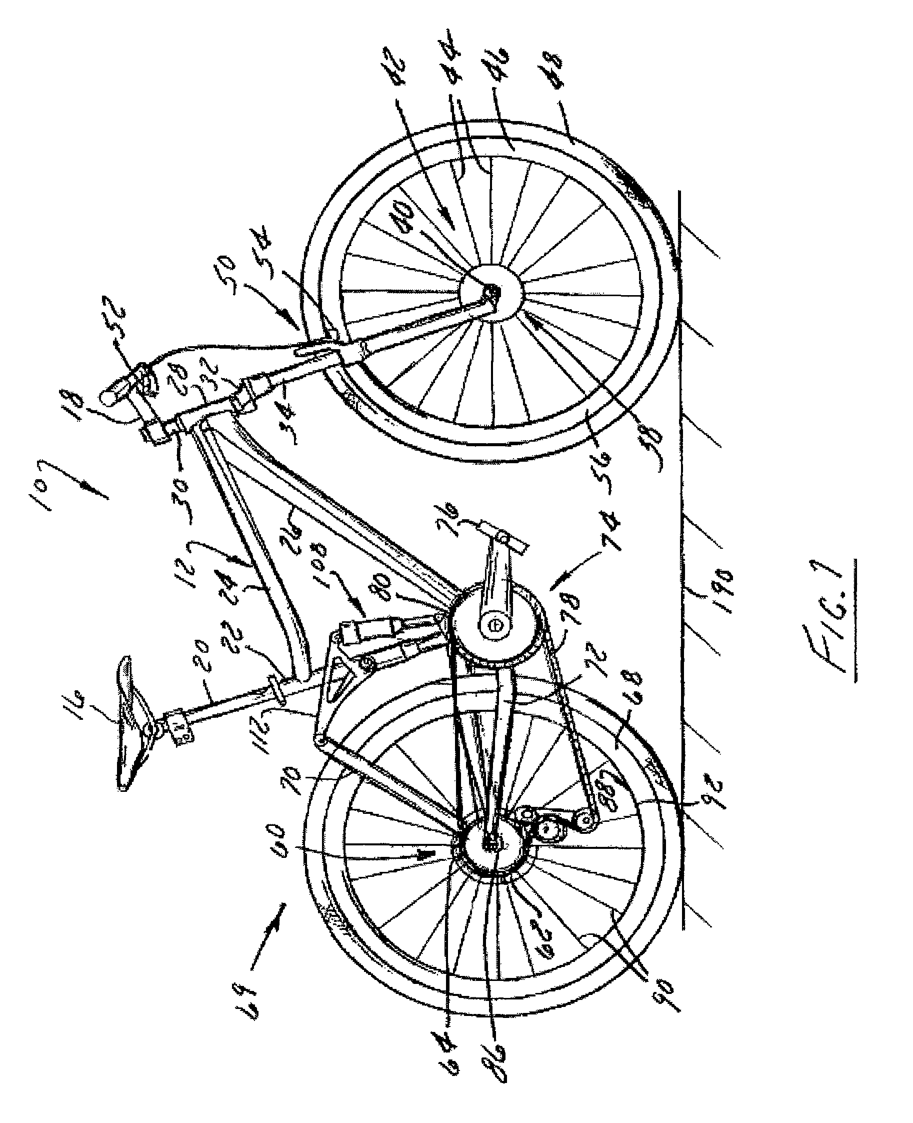
[0022]FIG. 1 shows a bicycle 10 having a frame assembly 12 equipped with a rear wheel suspension system according to the present invention. Bicycle 10 includes a seat 16 and handlebars 18 that are attached to frame assembly 12. A seat post 20 is connected to seat 16 and slidably engages a seat tube 22 of frame assembly 12. A top tube 24 and a down tube 26 extend forwardly from seat tube 22 to a head tube 28 of frame assembly 12. Handlebars 18 are connected to a stem 30 that passes through head tube 28 and engages a fork crown 32. A pair of forks 34 extend from generally opposite ends of fork crown 32 and are constructed to support a front wheel assembly 36 at an end of each fork or a fork tip 38. Fork tips 38 engage generally opposite sides of an axle 40 that is constructed to engage a hub 42 of front wheel assembly 36. A number of spokes 44 extend from hub 42 to a rim 46 of front wheel assembly 36. A tire 48 is engaged with rim 46 such that rotation of tire 48, relative to forks 34...


PUM


Abstract

A bicycle frame assembly having a number of rotatable members configured to absorb shocks and impacts associated with operation of the bicycle. The assembly includes a frame constructed to support a rider and a chain stay having a rearward end that extends toward a wheel hub and a forward end that is pivotably connected to the frame. An absorber is pivotably connected to the forward end of the chain stay and extends to a rocker arm that is pivotably connected to the frame. A seat stay is pivotably connected to a rearward end of the rocker arm and extends to the rearward end of the chain stay. The rearward ends of the seat stay and the chain stay are pivotably connected to rotate about a common axis.

Description

BACKGROUND OF THE INVENTION[0001]The present invention relates generally to bicycles and, more particularly, to a suspension system for a rear wheel of the bicycle.[0002]The primary structural component of a conventional two-wheel bicycle is the frame. On a conventional road bicycle, the frame is typically constructed from a set of tubular members assembled together to form the frame. For many bicycles, the frame is constructed from members commonly referred to as the top tube, down tube, seat tube, seat stays and chain stays, and those members are joined together at intersections commonly referred to as the head tube, seat post, bottom bracket and rear dropout. The top tube usually extends from the head tube rearward to the seat tube. The head tube, sometimes referred to as the neck, is a short tubular structural member at the upper forward portion of the bicycle which supports the handlebar and front steering fork, which has the front wheel on it. The down tube usually extends dow...

Claims


Application Information

Patent Timeline
Patent Type & Authority Patents(United States)
IPC IPC(8): B62K25/28B62K25/04
CPCB62K25/04B62K25/286
Inventor COLEGROVE, JAMESHOWES, DYLANGONZALEZ, JOSE
Owner TREK BICYCLE CORPORATION
Why Eureka
Try Eureka