Electrical connector having matched impedance by contacts having node arrangement

a technology of matched impedance and contacts, applied in the direction of coupling device connection, coupling contact member engagement/disengagement, coupling parts, etc., can solve the problem of not being able to manufacture ideal electrical connectors, circuits cannot be normally electrically communicated, performance of the whole system weakened or reduced, etc. problem, to achieve the effect of increasing the capacit increasing cross-sectional area, and reducing characteristic impedance of conductive contacts

Inactive Publication Date: 2010-11-23
HON HAI PRECISION IND CO LTD
View PDF20 Cites 19 Cited by
  • Summary
  • Abstract
  • Description
  • Claims
  • Application Information

AI Technical Summary

Benefits of technology

[0008]Accordingly, an object of the present invention is to provide an electrical connector including conductive contacts which has characteristic impedance matching with a given impedance and are positioned precisely.
[0011]The electrical connector according to the embodiments of the present invention disposes a node in the extension portion of the conductive contact. The extension portion has a longer length, so the extension portion has an enough space to dispose the node properly for matching characteristic impedance of the conductive contact. For example, capacitance of the conductive contact can be increased by increasing the cross-sectional area of the extension portion of the conductive contact, thereby reducing characteristic impedance of the conductive contact. In contrary, capacitance of the conductive contact can be reduced by reducing the cross-sectional area of the extension portion of the conductive contact, thereby increasing characteristic impedance of the conductive contact. Furthermore, capacitance of the conductive contact can be increased by decreasing the space between the extension portions of the conductive contact, thereby reducing characteristic impedance of the conductive contact. In contrary, capacitance of the conductive contact can be decreased by increasing the space between the extension portions of the conductive contact, thereby increasing characteristic impedance of the conductive contact. The positioning portion disposed in the insulative housing can cooperate with the node to restrict movement of the node, so as to position the conductive contact precisely. Therefore, by adopting the simple structure, the electrical connector in accordance with the embodiments of the present invention not only can match characteristic impedance of the conductive contact to match with given impedance, but also can assure precise positioning of the conductive contact.

Problems solved by technology

Or else, the performance of the whole system will be weakened or reduced.
But actually, it is no possible to manufacture the ideal electrical connectors.
Once a conductive contact is displaced, the electrical connector is mounted improperly, so that the circuit can't be normally electrically communicated.

Method used


Image

  • Electrical connector having matched impedance by contacts having node arrangement
  • Electrical connector having matched impedance by contacts having node arrangement
  • Electrical connector having matched impedance by contacts having node arrangement

Examples


Embodiment Construction

[0021]Hereinafter, in order to make the above objects, features and advantages to be easily understood, embodiments of the present invention will be described in detail with reference to the accompanying drawings.

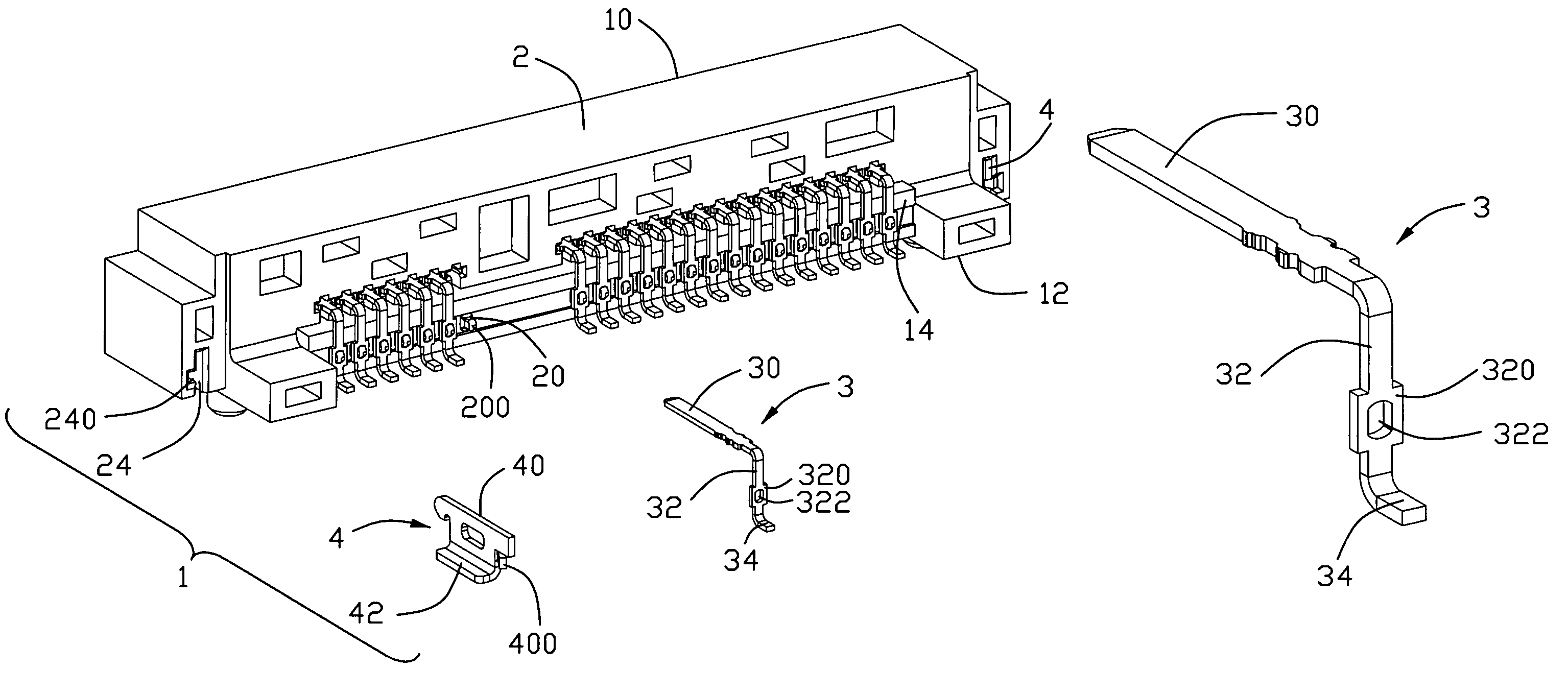
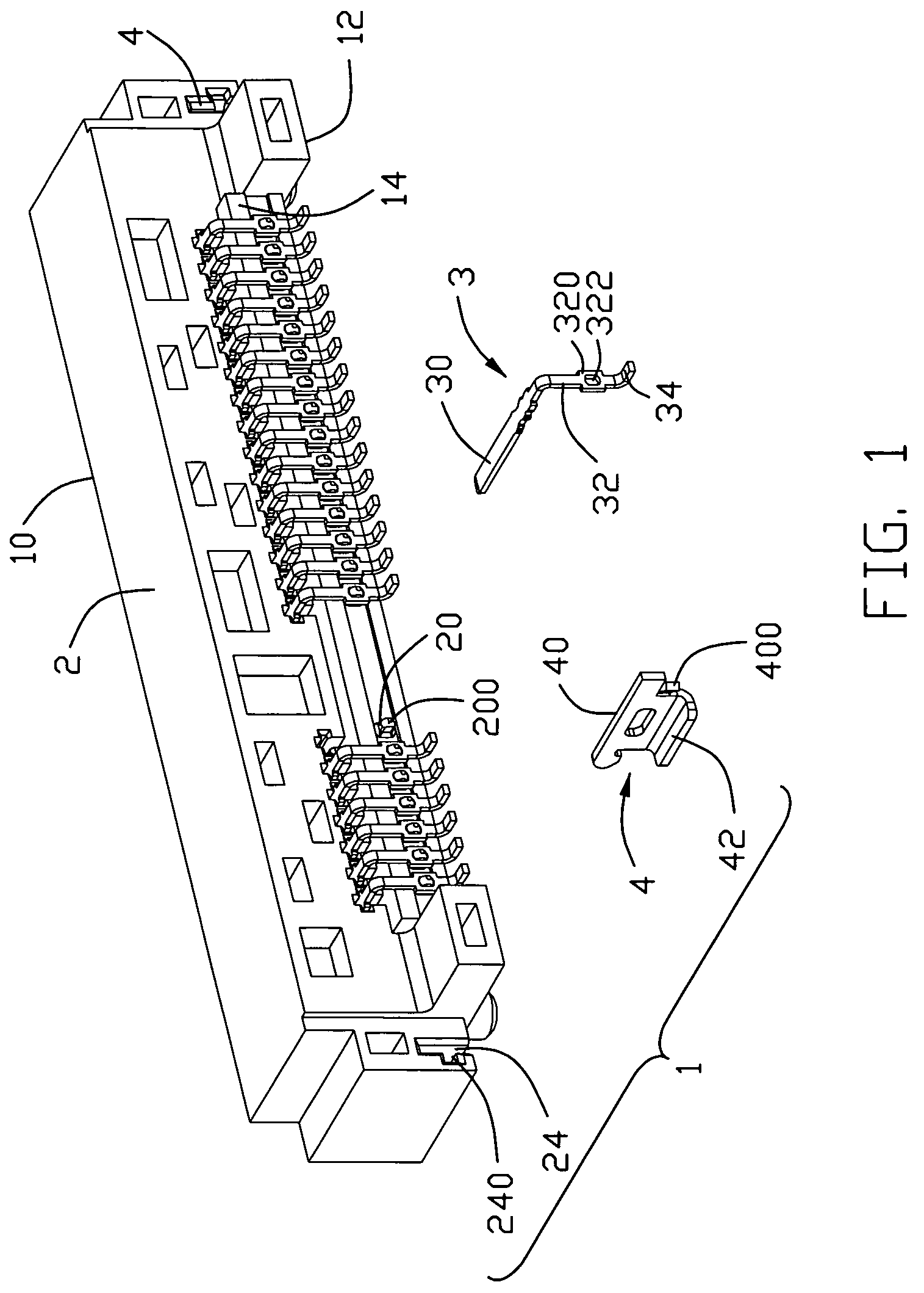
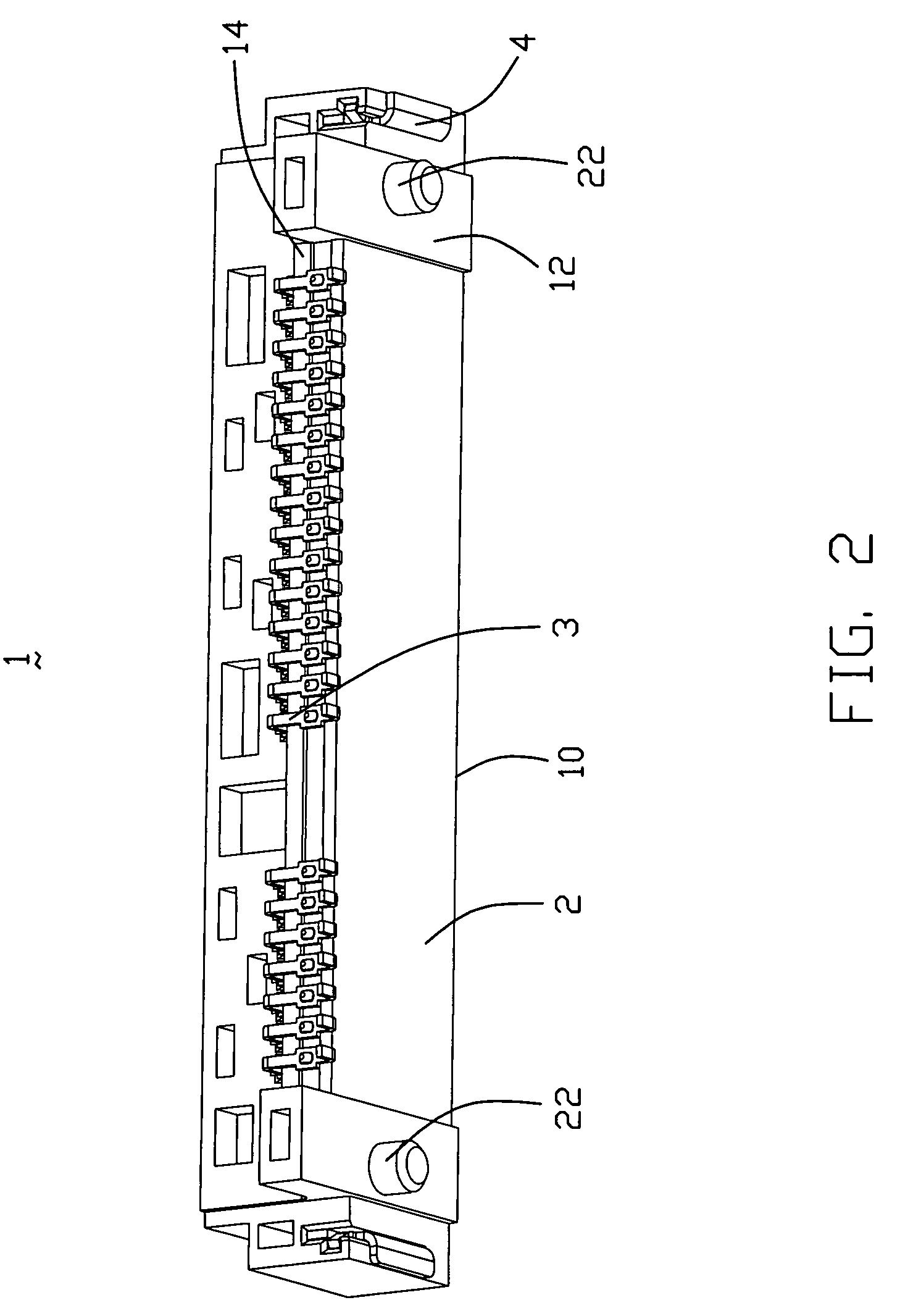
[0022]Referring to FIG. 1 to FIG. 5, an electrical connector 1 in accordance with a first embodiment of the present invention has a mating section 10 in a front thereof, and a mounting surface 12 in a bottom thereof and a rear surface 14 opposite to the mating section 10. The electrical connector 1 comprises an insulative housing 2, a plurality of conductive contacts 3 received in the insulative housing 2 and a pair of latching members 4 retained in the insulative housing 2.

[0023]A plurality of positioning portions 20 are disposed in the rear surface 14, and a protrusion 200 is disposed in each positioning portion. A pair of positioning posts 22 are respectively disposed in opposite longitudinal ends of the insulative housing 2 and protrudes from the mounting surface 12 for...


PUM


Abstract

An electrical connector includes an insulative housing and a number of conductive contacts received in the insulative housing. Each conductive contact has a contacting portion, an engaging portion and an extension portion electrically connecting with the contacting portion and the engaging portion. A node is disposed in the extension portion for matching characteristic impedance of the conductive contact, and a positioning portion is disposed in the insulative housing corresponding to the node for cooperating with the node to restrict movement of the node. The electrical connector in accordance with the present invention can match characteristic impedance of the conductive contact to realize impedance match and can assure precise positioning of the conductive contact.

Description

BACKGROUND OF THE INVENTION[0001]1. Field of the Invention[0002]The present invention is generally related to the art of electrical connector for use in transmitting high frequency signals and more particularly to methods and structures for controlling the impedance in electrical connector to match given impedance.[0003]2. Description of Related Art[0004]Electrical connectors are widely applied to the electronic industry. For example, the electrical connector is used for electrical connection and signal transmittance between elements, assemblies or systems of an electronic device.[0005]In today's high-speed electronic devices, it is required to optimize interconnection routes among all the components for improving signal transmitting characteristic. Or else, the performance of the whole system will be weakened or reduced. In an ideal case, signal can be transmitted from one circuit to another circuit via the electrical connectors without loss and delay, and the electrical connectors...

Claims


Application Information

Patent Timeline
Patent Type & Authority Patents(United States)
IPC IPC(8): H01R13/62
CPCH01R12/57H01R12/712H01R13/41Y10S439/941H01R12/7011
Inventor ZHU, YU
Owner HON HAI PRECISION IND CO LTD
Why Eureka
Try Eureka