Display device and board supporting structure

a technology of supporting structure and display device, which is applied in the direction of static indicating device, manufacturing tools, instruments, etc., can solve the problems of thickening of display device and damage to the display board due to engagement member, so as to facilitate the fixation improve the performance stability of the display board, and improve the reliability of the electrical insulation

Active Publication Date: 2010-11-23
LG ELECTRONICS INC
View PDF23 Cites 20 Cited by
  • Summary
  • Abstract
  • Description
  • Claims
  • Application Information

AI Technical Summary

Benefits of technology

[0013]An object of the present invention is to provide a display device and a board supporting structure capable of installing a board to a main frame so that a board fixedly installed to a main frame of a display device is insulated from the main frame to prevent electric short while the display device is not thickened.
[0014]Another object of the present invention is to provide a display device and a board supporting structure capable of preventing direct contact between an engagement member, such as a fixing screw, and a board in fixing the board to a main frame.
[0015]A further another object of the present invention is to provide a display device and a board supporting structure capable of facilitating the fixation of a board with respect to a main frame.
[0016]A still further another object of the present invention to provide a display device and a board supporting structure capable of improving the performance stability of a board by improving reliability of the electrical insulation between a main frame and a board.
[0023]Accordingly, an increase in thickness of the display device due to installation of the board is reduced, the performance reliability of the board is improved, the installation of the board is facilitated, and damage to the board is prevented.

Problems solved by technology

However, the fixing of the board to the main frame through the ‘┐’ shaped protrusion is problematic in that the display device is thickened because a space as high as the vertical heights of various circuit components mounted on the board is needed.
Also, because the protrusion is coupled to the board in a state that a coupling member is in direct contact with the board, damage to the board may occur due to the engagement member.

Method used


Image

  • Display device and board supporting structure
  • Display device and board supporting structure
  • Display device and board supporting structure

Examples


first embodiment

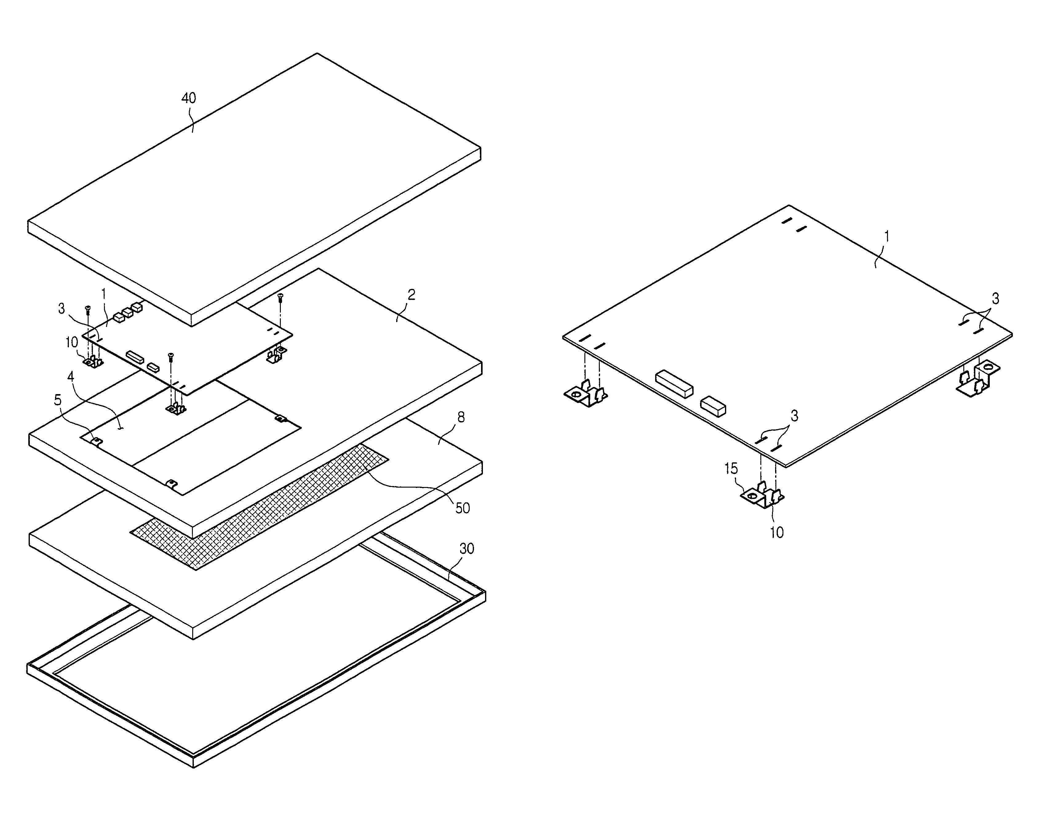
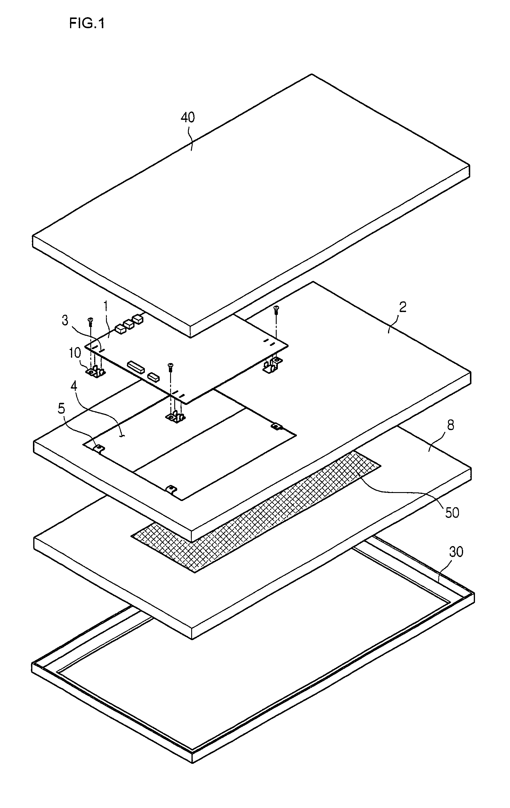
[0035]FIG. 1 is an exploded perspective view of a display device according to the present invention.

[0036]Referring to FIG. 1, the display device according to the present invention includes a front cabinet 30 and a back cover 40 respectively protecting front and rear sides of the display device, a display module 8 providing an image actually, a main frame 2 fixed to a rear side of the display module 8, supporting a display module 8 and reinforcing the strength, and a board 1 installed at the main frame 2.

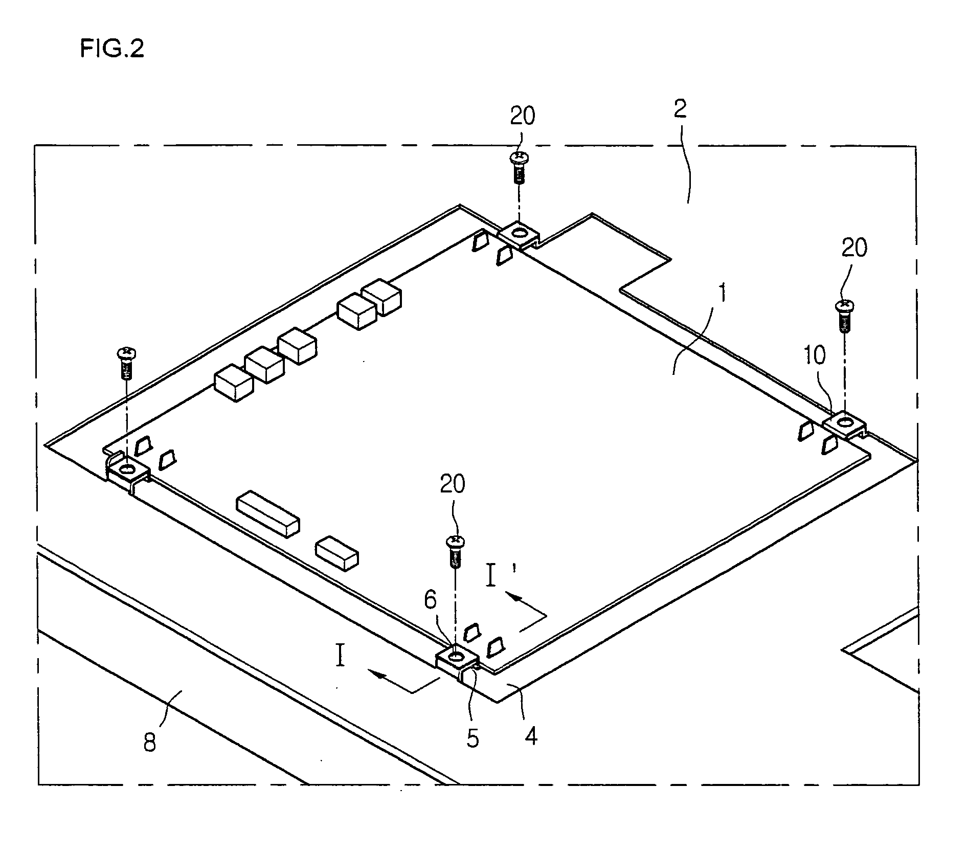
[0037]Also, the board 1 is fixed to the main frame 2 by a connection member 10, and a place where the board 1 is placed is aligned with a receiving portion 4.

[0038]Also, in order to provide a portion receiving the board 1, a receiving portion 4 is formed in the main frame 2. The receiving portion 4 may be formed in a shape having a height equal to the entire height of the main frame 2 and a predetermined area corresponding to an area of the board 1, or the receiving portion 4 may be...

second embodiment

[0073]The second embodiment of the present invention is identical to the first embodiment, except for a connection member and structures of a board and a main frame at their portions where the connection member is coupled. Therefore, the connection member and the portions related thereto are described in detail, portions without specific description will cite the description of the first embodiment, and detailed description thereof will be omitted.

[0074]FIG. 6 is an exploded perspective view of a display device according to a second embodiment of the present invention, and FIG. 7 is a cross-sectional view taken along line II-II′ of FIG. 6.

[0075]Referring to FIGS. 6 and 7, the connection member 60 according to the present embodiment is formed in a single plane shape, and both ends of the connection member 60 are connected to a board 1 and a main frame 2 by a connection screw, respectively.

[0076]The connection member 60 is formed straight to connect the main frame 2 with the board 1, ...

third embodiment

[0081]The third embodiment of the present invention is identical to the second embodiment, except for a structure of a main frame at its portion to which a connection member is coupled. Therefore, only the portion related to the main frame to which the connection member is mounted will be described in detail, portions without specific description will cite the description of the aforementioned embodiment, and detailed description thereof will be omitted.

[0082]FIG. 8 is a cross-sectional view of a board supporting structure of a display device according to the present embodiment.

[0083]Referring to FIG. 8, in the present embodiment, a frame-side connection-member fixing portion 5 is provided to the main frame 2 like the first embodiment. For this reason, an interval between the board 1 and the display module 8 becomes long, and therefore, an insulation material 50 may not be needed.

[0084]However, even in this case, forming the insulation material 50 as in other embodiments may more ef...


PUM

PropertyMeasurementUnit
supporting structureaaaaaaaaaa
heightaaaaaaaaaa
areaaaaaaaaaaa

Abstract

Provided are a display device and a board supporting structure. The board supporting structure includes: a board; a main frame to which the board is fixed; a receiving portion formed at the main frame and on which the board is placed; and a connection member being a separate component fixing the board to the main frame and including a first portion coupled to the main frame and a second portion coupled to the board. Accordingly, an increase in thickness of the display device due to installation of the board is reduced, the performance reliability of the board is improved, the installation of the board is facilitated, and damage to the board is prevented.

Description

BACKGROUND OF THE INVENTION[0001]1. Field of the Invention[0002]The present invention relates to a display device, and particularly, to a board supporting structure of a display device for fixing a board to a frame placed within a slim flat-display device. More particularly, the present invention relates to a board supporting structure capable of conveniently, simply and stably installing within a small area a board on which various circuits driving a display device are installed.[0003]2. Description of the Related Art[0004]In general, a display device displays an image upon receiving an electric signal. Examples of the display device include a cathode ray tube, a liquid crystal display device (LCD), a plasma display device (PDP), and the like.[0005]Because the display device is an apparatus for displaying an image upon receiving an electric signal, it is essential to install a printed circuit board (hereinafter, referred to as a board) in order to display an image on a surface of a...

Claims


Application Information

Patent Timeline
Patent Type & Authority Patents(United States)
IPC IPC(8): H05K7/14
CPCH05K7/142Y10T29/53174
Inventor KIM, DONG WOO
Owner LG ELECTRONICS INC
Why Eureka
Try Eureka