
Electronic video image stabilization

a technology of electronic image stabilization and video image, which is applied in the field of video processing, can solve the problems of blurry image, shaking or jitter in video image, and image captured by such devices are more susceptible to quality degradation, shaking or jitter,

Active Publication Date: 2010-11-23
QUALCOMM INC
View PDF9 Cites 9 Cited by
  • Summary
  • Abstract
  • Description
  • Claims
  • Application Information

AI Technical Summary

Benefits of technology

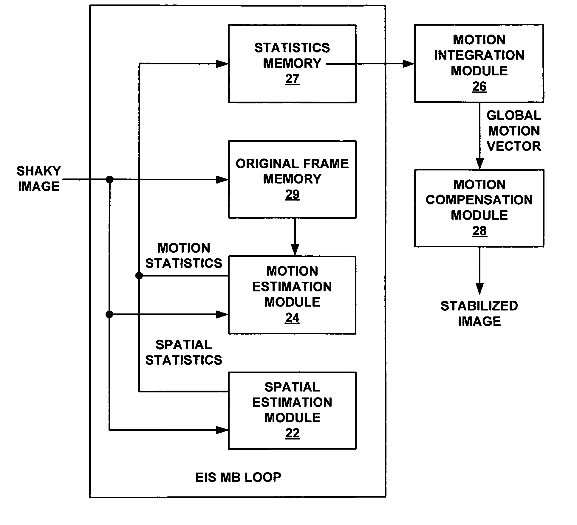
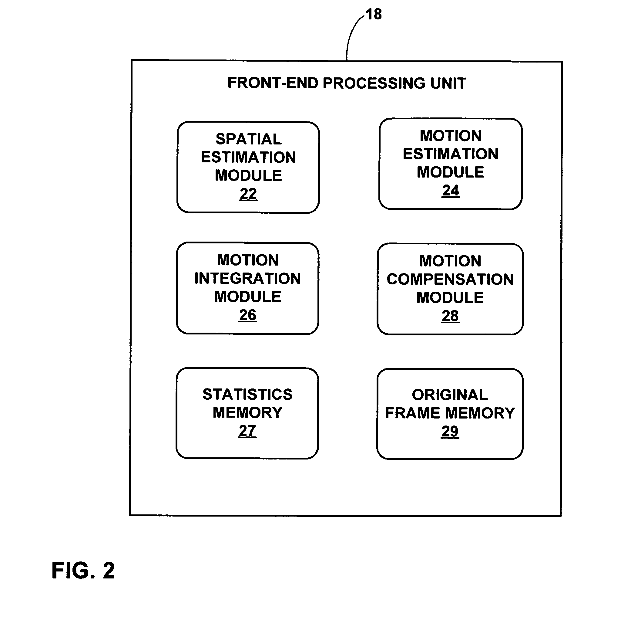
This patent describes techniques for stabilizing video images by detecting and compensating for shaking and motion in the captured scene. The techniques involve dividing the video frame into non-overlapping macroblocks, calculating spatial and motion statistics for each macroblock, and integrating these statistics to determine a global motion vector. An offset is then applied to the frame based on the global motion vector to compensate for shake. The patent also provides a device and method for performing these techniques, as well as a computer-readable medium containing instructions for implementing the techniques. The technical effect of this patent is to provide a more efficient and effective technique for stabilizing video images, which can differentiate between shaking and genuine motion.

Problems solved by technology

As imaging devices become lighter and smaller, the images captured by such devices are more susceptible to quality degradation due to inadvertent shaking.
In still image capture, the shake may result in a blurry image.
In video capture, the shake may result in shaking or jitter in the video image.
Shake and jitter can make it difficult for the human visual system to focus and concentrate on a region or object of interest within the video.
When this shake appears in conjunction with genuine motion in the video, the adverse effects can be compounded.
Some EIS systems work well in many situations, but may suffer from an inability to differentiate genuine motion from unwanted shaking.

Method used


Image

  • Electronic video image stabilization
  • Electronic video image stabilization
  • Electronic video image stabilization

Examples


Embodiment Construction

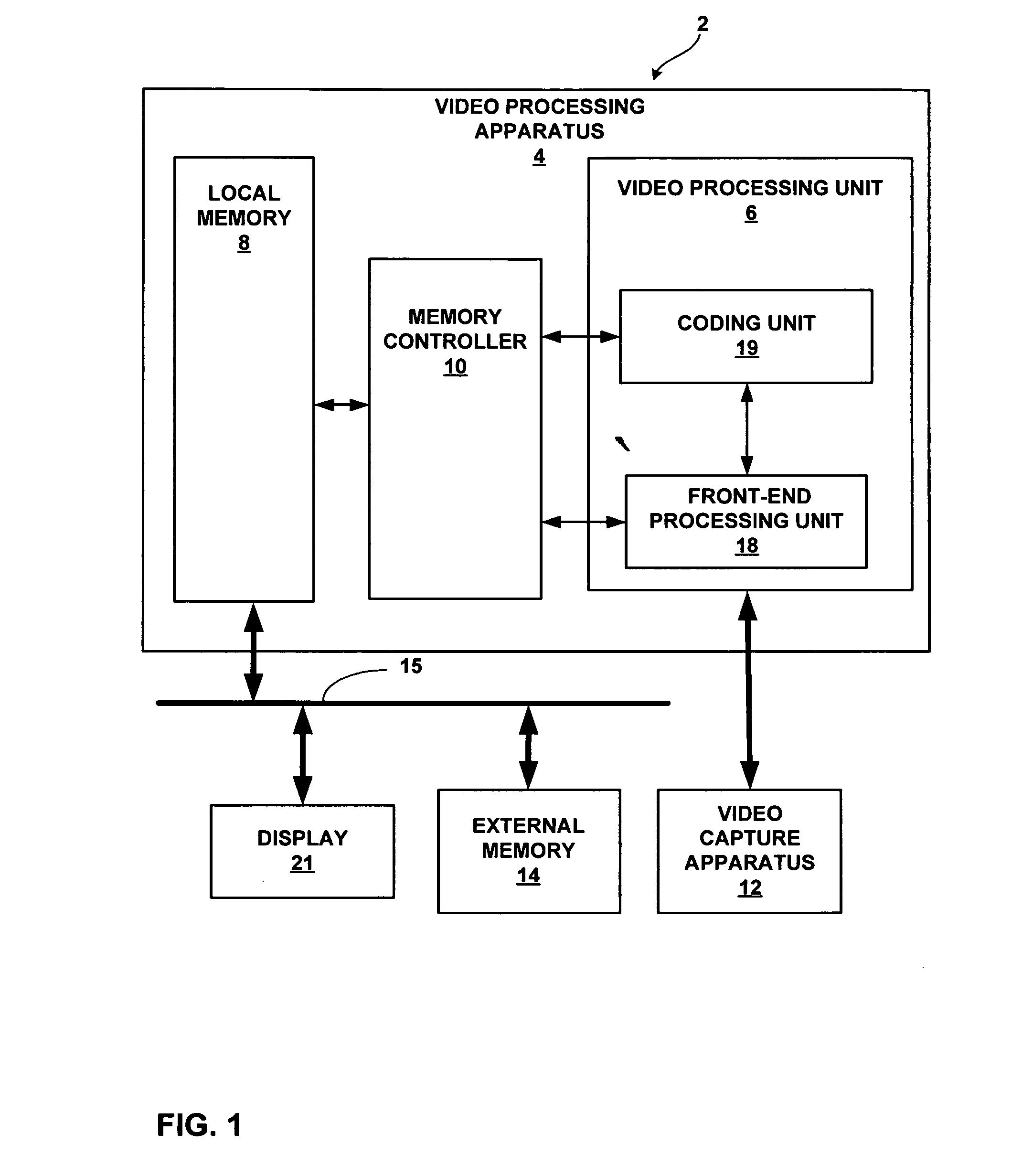
[0023]FIG. 1 is block diagram of an exemplary device 2 that may implement scalable electronic image stabilization techniques in accordance with this disclosure. Device 2 may form part of a digital video processing device capable of coding video data. The digital video processing device may process video obtained by a video capture device, such as a video camera, or a video archive that stores previously captured video. By way of example, device 2 may form part of a digital video camera, a laptop computer, a desktop computer, a wireless communication device such as a cellular or satellite radio telephone, a personal digital assistant (PDA), or any device with digital video capabilities. Video capture devices may be susceptible to undesirable shaking that undermines video quality. Motion estimation can be used for image stabilization. However, motion may occur due to either unintended shaking of the video capture device or intended movement resulting from panning, zooming, tilting or ...


PUM


Abstract

This disclosure describes electronic video image stabilization techniques for imaging and video devices. The techniques involve determining motion and spatial statistics for individual macroblocks of a frame, and determining a global motion vector for the frame based on the statistics of each of the macroblocks. In one embodiment, a method of performing electronic image stabilization includes performing spatial estimation on each of a plurality of macroblocks within a frame of an image to obtain spatial statistics for each of the macroblocks, performing motion estimation on each of the plurality of macroblocks to obtain motion statistics for each of the macroblocks, integrating the spatial statistics and the motion statistics of each of the macroblocks to determine a global motion vector for the frame, and offsetting the image with respect to a reference window according to the global motion vector.

Description

[0001]This application claims the benefit of U.S. Provisional Application Ser. No. 60 / 790,514, filed Apr. 6, 2006, the entire content of which is incorporated herein by reference.TECHNICAL FIELD[0002]The disclosure relates to video processing and, more particularly, techniques for electronic image stabilization in electronic video applications.BACKGROUND[0003]As imaging devices become lighter and smaller, the images captured by such devices are more susceptible to quality degradation due to inadvertent shaking. In still image capture, the shake may result in a blurry image. In video capture, the shake may result in shaking or jitter in the video image. Shake and jitter can make it difficult for the human visual system to focus and concentrate on a region or object of interest within the video. When this shake appears in conjunction with genuine motion in the video, the adverse effects can be compounded. In either case, the quality of the viewing experience of the video or image is r...

Claims


Application Information

Patent Timeline
Patent Type & Authority Patents(United States)
IPC IPC(8): G06K9/40H04N23/40
CPCH04N5/23248H04N5/23254H04N5/23264H04N5/23267H04N19/14H04N19/527H04N23/68H04N23/6811H04N23/682H04N23/683
Inventor NAGARAJ, RAGHAVENDRA C.MALAYATH, NARENDRANATH
Owner QUALCOMM INC
Learn More