Sub-surface tubing spacer means for direct expansion heating/cooling systems

a technology of direct expansion and subsurface tubing, which is applied in the direction of domestic cooling equipment, heat pumps, lighting and heating equipment, etc., can solve the problems of limiting the ability to install dx systems in various applications, and affecting the installation of dx systems

Inactive Publication Date: 2010-11-30
EARTH TO AIR SYST
View PDF35 Cites 5 Cited by
  • Summary
  • Abstract
  • Description
  • Claims
  • Application Information

AI Technical Summary

Benefits of technology

[0015]It is an object of the present invention to further enhance and improve predecessor DX system sub-surface tubing installation means by the utilization of spacing devices, such as spacer fins or the like, to ensure all sub-surface tubing is surrounded by a protective heat-conductive grout in a manner so as to avoid direct tubing contact with potentially / actually corrosive surrounding sub-surface element conditions. The subject invention may be utilized to protect larger diameter sub-surface metal tubing used to contain smaller diameter refrigerant transport tubing / lines. Alternatively, the subject invention may be utilized to protect both the subsurface liquid refrigerant transport lines, whether insulated and / or un-insulated, and the un-insulated subsurface vapor refrigerant transport lines when such refrigerant transport lines are directly installed into the ground absent a containment pipe.

Problems solved by technology

While cathodic protection works well for near surface applications, it is more difficult and expensive to utilize in vertically oriented deep well / borehole tubing applications (a deep well / borehole application is herein defined as being in excess of 100 feet deep).
Further, the simple avoidance of tubing installations in areas of corrosive soils restricts the ability to install DX systems in various applications due to unavailability of sufficient non-corrosive land area for geothermal heat transfer.
Further, since some sub-surface environments can be corrosive to copper, in such instances it is not desirable to push the exposed copper line against the native earth.

Method used


Image

  • Sub-surface tubing spacer means for direct expansion heating/cooling systems
  • Sub-surface tubing spacer means for direct expansion heating/cooling systems

Examples


Embodiment Construction

[0028]The following detailed description is of the best presently contemplated mode of carrying out the invention. The description is not intended in a limiting sense, and is made solely for the purpose of illustrating the general principles of the invention. The various features and advantages of the present invention may be more readily understood with reference to the following detailed description taken in conjunction with the accompanying drawings.

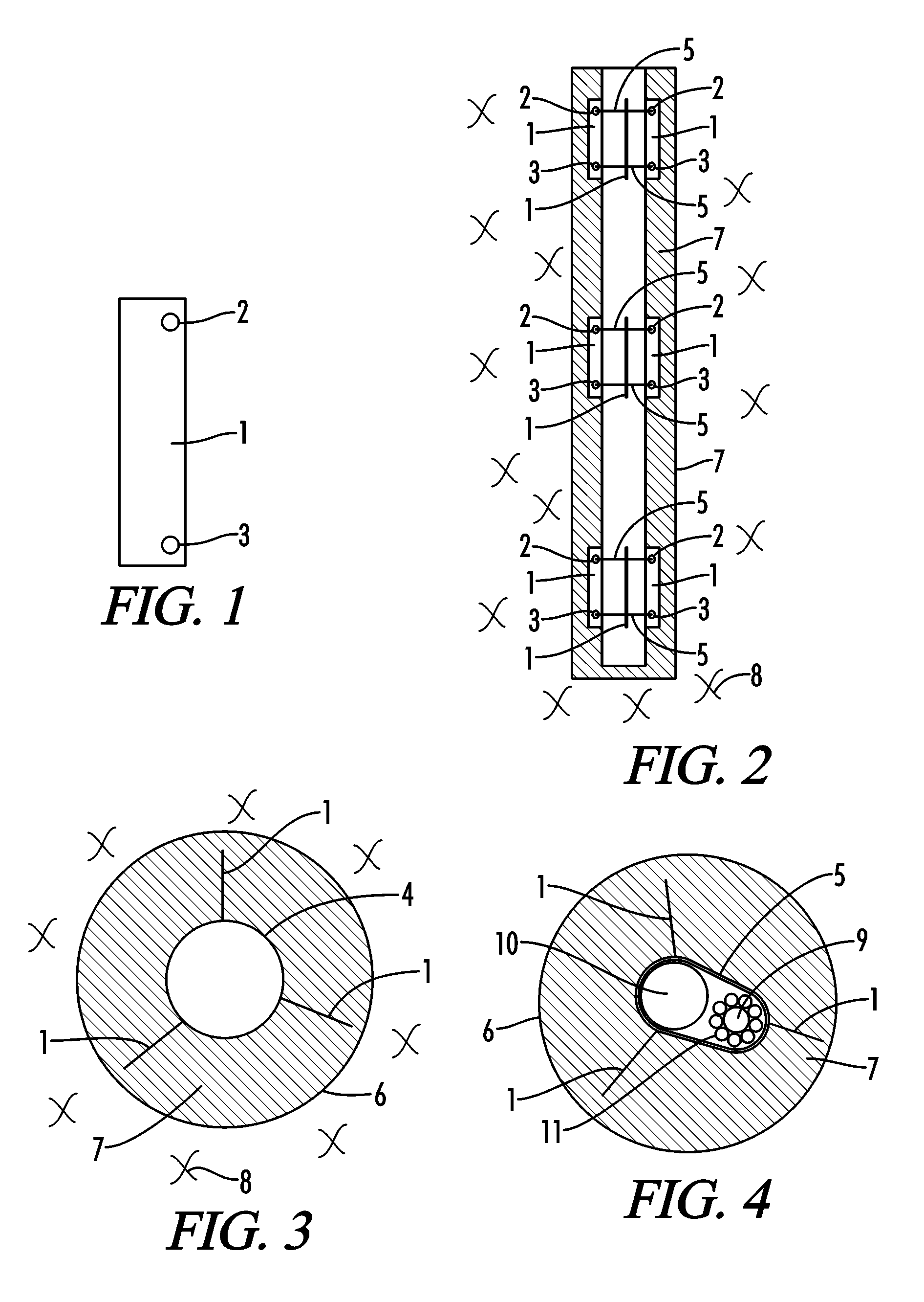
[0029]Referring now to the drawings in detail, where like numerals refer to like parts or elements, there is shown in FIG. 1 a side view of a spacing device comprised of a spacer fin 1, with an upper hole 2 and a lower hole 3 respectively drilled or punched through the spacer fin 1 for purposes of securing the spacer fin 1 in place.

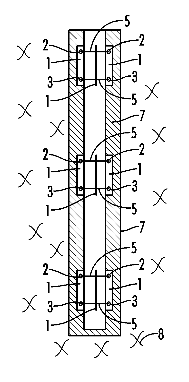
[0030]FIG. 2 shows a side view of a series of three, vertically oriented, respective spacer devices comprised of spacer fins 1 secured around a refrigerant transport tube 4 (which could alternatively be a r...


PUM


Abstract

A direct expansion geothermal heat exchange system with spacer fins attached to at least one of a sub-surface refrigerant transport tubing containment pipe and to sub-surface refrigerant transport tubing, so as to ensure the sub-surface pipe/tubing does not come into direct contact with the ground and is surrounded/encased by a thermally conductive grout that is resistant to corrosive sub-surface elements.

Description

CROSS-REFERENCES TO RELATED APPLICATIONS[0001]This application is a Non-Provisional Utility application which claims benefit of co-pending U.S. Provisional Patent Application Ser. No. 60 / 471,585 filed May 19, 2003, entitled “Deep Well-Long Trench Direct Expansion Heating / Cooling System and Retrofit Design” which is hereby incorporated by reference.[0002]A portion of the disclosure of this patent document contains material that is subject to copyright protection. The copyright owner has no objection to the facsimile reproduction by anyone of the patent document or the patent disclosure, as it appears in the U.S. Patent and Trademark Office patent file or records, but otherwise reserves all copyright rights whatsoever.STATEMENT REGARDING FEDERALLY SPONSORED RESEARCH OR DEVELOPMENT[0003]Not ApplicableREFERENCE TO SEQUENCE LISTING OR COMPUTER PROGRAM LISTING APPENDIX[0004]Not ApplicableBACKGROUND OF THE INVENTION[0005]The present invention relates to an improved means, in a direct excha...

Claims


Application Information

Patent Timeline
Patent Type & Authority Patents(United States)
IPC IPC(8): F25D23/12F24J3/08
CPCF24J3/082F25B30/06Y02E10/125F28F2240/00F24T10/13Y02E10/10
Inventor WIGGS, B. RYLAND
Owner EARTH TO AIR SYST
Why Eureka
Try Eureka