Stent with spiral side-branch

a technology of side brackets and stents, which is applied in the field of stents with spiral sides, can solve the problems of many prior art stents not being wholly satisfactory for us

Inactive Publication Date: 2010-11-30
BOSTON SCI SCIMED INC
View PDF330 Cites 104 Cited by
  • Summary
  • Abstract
  • Description
  • Claims
  • Application Information

AI Technical Summary

Problems solved by technology

Many prior art stents however are not wholly satisfactory for use where the site of desired application of the stent is juxtaposed or extends across a bifurcation in an artery or vein such, for example, as the bifurcation in the mammalian aortic artery into the common iliac arteries.

Method used


Image

  • Stent with spiral side-branch
  • Stent with spiral side-branch
  • Stent with spiral side-branch

Examples


Embodiment Construction

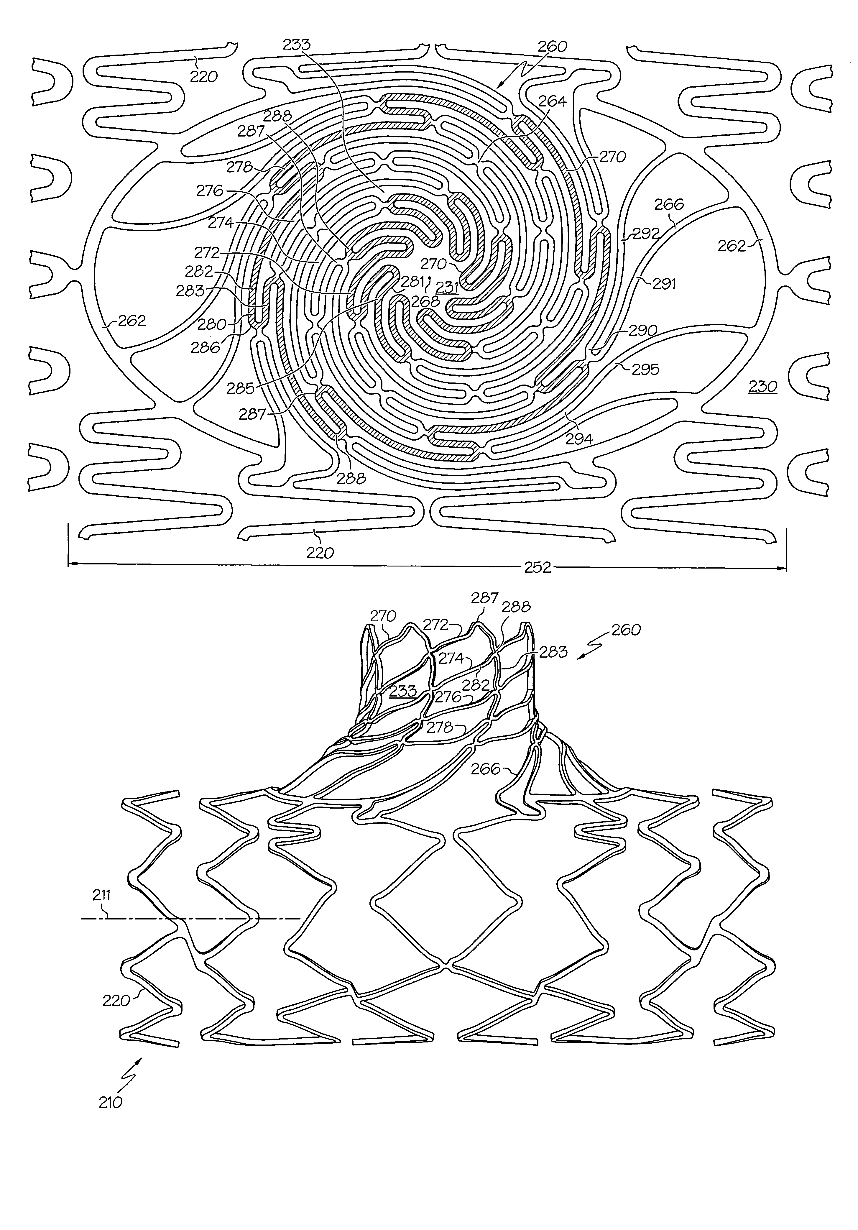
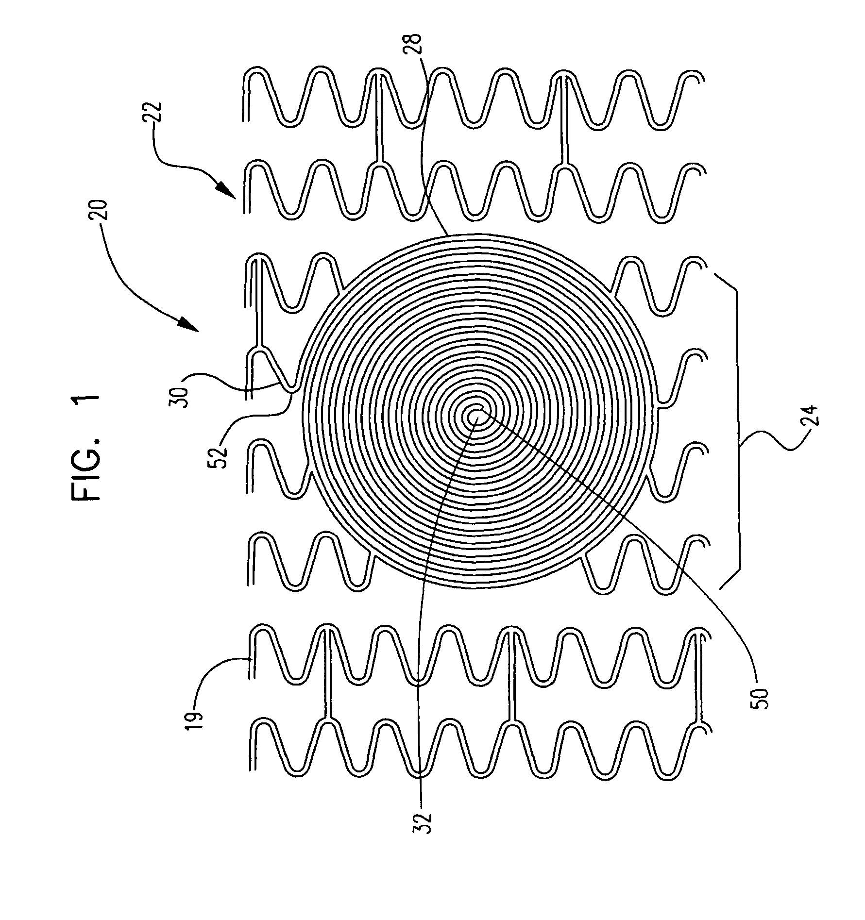
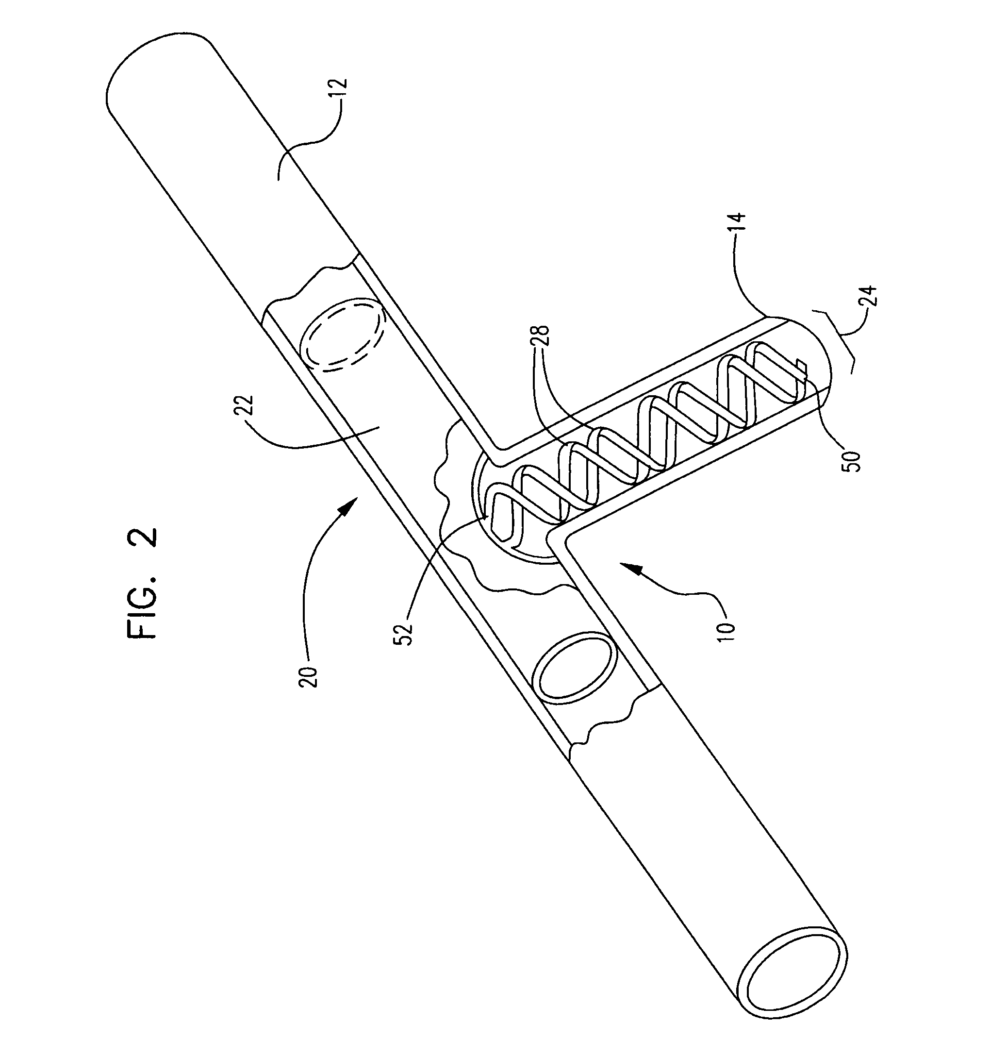
[0045]While this invention may be embodied in many different forms, there are described in detail herein specific embodiments of the invention. This description is an exemplification of the principles of the invention and is not intended to limit the invention to the particular embodiments illustrated.

[0046]For purposes of this disclosure, like reference numerals in the figures shall refer to like features unless otherwise indicated.

[0047]Some examples of stents having a side opening and methods of deploying such stents are disclosed in U.S. Pat. Nos. 5,596,020 and 6,835,203, the entire disclosures of which are hereby incorporated herein in their entireties.

[0048]The entire disclosures of U.S. Pat. Nos. 5,922,021, 6,123,721, 6,334,870, 6,478,816, 6,348,065 and 6,325,826 are hereby incorporated herein by reference in their entireties. The entire disclosures of U.S. Provisional Application No. 60 / 844,011, filed Sep. 12, 2006, and U.S. patent application Ser. No. 11 / 519,552, filed Sep....


PUM


Abstract

In at least one embodiment, a stent comprises a plurality of interconnected framework members defining a plurality of cells. A portion of the interconnected framework members comprise a side branch structure having an inner side branch cell that is shaped differently from other cells of the stent. The side branch structure further comprises a serpentine ring extending around the inner side branch cell, the serpentine ring having alternating struts and turns. Each strut includes curvature along its length and is oriented with the curvature being concave with respect to a center point of the inner side branch cell.

Description

CROSS-REFERENCE TO RELATED APPLICATIONS[0001]This Application claims the benefit of and is a continuation-in-part of U.S. patent application Ser. No. 11 / 273186, filed Nov. 14, 2005, the entire contents of which is hereby incorporated herein by reference.STATEMENT REGARDING FEDERALLY SPONSORED RESEARCH[0002]Not ApplicableBACKGROUND OF THE INVENTION[0003]Stents, grafts, stent-grafts and similar implantable medical devices, collectively referred to hereinafter as stents, are radially expandable endoprostheses which are typically intravascular implants capable of being implanted transluminally and enlarged radially after being introduced percutaneously. Stents may be implanted in a variety of body lumens or vessels such as within the vascular system, urinary tracts, bile ducts, etc. Stents may be used to reinforce body vessels and to prevent restenosis following angioplasty in the vascular system. They may be self-expanding or expanded by an internal radial force, such as when mounted o...

Claims


Application Information

Patent Timeline
Patent Type & Authority Patents(United States)
IPC IPC(8): A61F2/06
CPCA61F2/856A61F2/91A61F2/915A61F2002/91525A61F2002/91533A61F2002/91558A61F2002/91575A61F2220/005A61F2220/0058A61F2230/005A61F2230/0091
Inventor YADIN, AMNON
Owner BOSTON SCI SCIMED INC
Why Eureka
Try Eureka