
Welding system and consumable electrode welding method

a welding system and electrode technology, applied in the field of welding system and consumable electrode welding method, can solve the problems of buckled welding wire b>101/b>, reduce useless time, increase the speed of follow-up performance of the actuator which moves the welding torch, and prevent overshooting.

Active Publication Date: 2010-11-30
PANASONIC CORP
View PDF13 Cites 12 Cited by
  • Summary
  • Abstract
  • Description
  • Claims
  • Application Information

AI Technical Summary

Benefits of technology

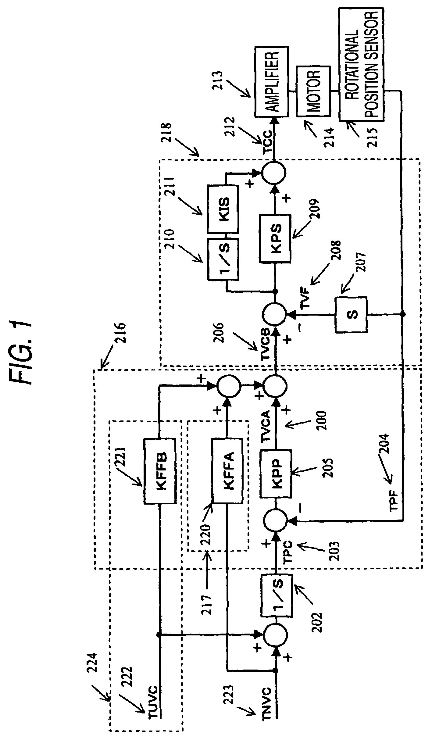
[0031]The reason why not a position component but the velocity component is input to the control loop is that the position component requires great significant digit including all of the operation range of the robot thereby to increase load on data processing.
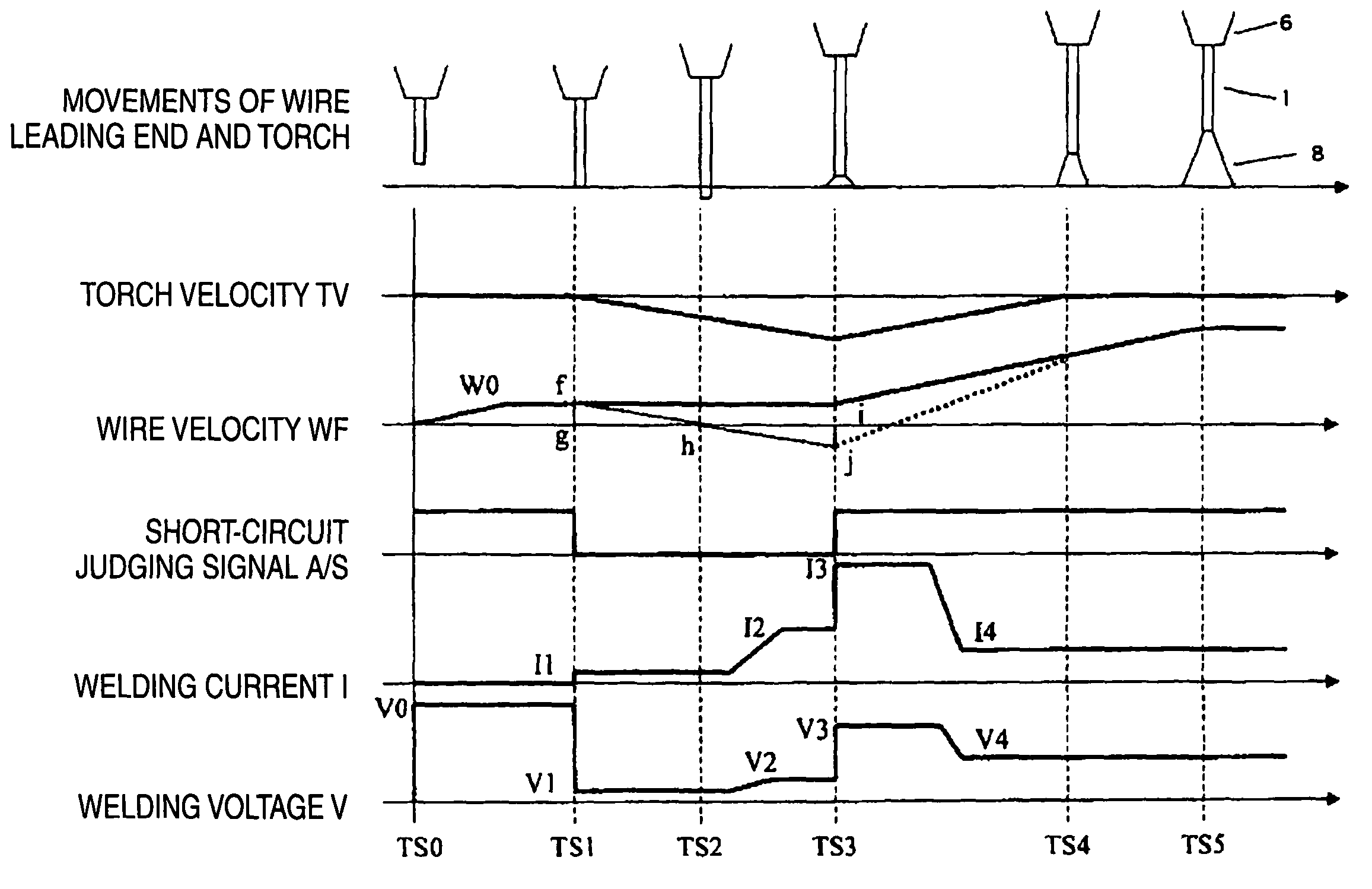
[0066]From the above result, it is known that: between the TS0′ and the TS2′ in the conventional arc start processing, since the deceleration starts after the detection of short-circuit at the TS1′, when the follow-up delay is smaller ever if the velocity overshoot is large, that is, when KFF is set at 1.0, the moving amount after the short-circuit detection at the TS1′ can be made smaller; and risky possibility of buckling of the welding wire 101 is reduced.
[0069]An object of the invention is to provide a consumable electrode type welding process which can reduce the useless time in arc generation sequence which the conventional consumable electrode type welding process has included, without generating buckling and spatter of a welding wire.
[0071]Further, a consumable electrode type welding process of the invention, using a welding system including a wire feeding unit which supplies a welding wire to a welding torch, an actuator which holds the welding torch and moves the welding torch, a controller which has a position control system and controls the actuator, and a welding power supply unit which applies weld output between an workpiece and the welding wire, moves the welding torch by the actuator in a direction separating from the workpiece while the welding wire is being supplied, thereby to control the velocity of the welding wire for the workpiece. Herein, the process is characterized in that the controller includes, separately from the position control system, a dedicated separation control system for controlling the actuator in the direction where the welding torch is separated from the workpiece.
[0072]According to this process, in the weld starting time, by the unidirectional operation by which the actuator separates the torch, the velocity of the welding wire for the workpiece can be controlled. Therefore, vibration due to reversal of the torch velocity is not generated. Further, the velocity follow-up performance of the actuator which moves the welding torch is increased by means of the dedicated separation control system, whereby the response time and the acceleration and deceleration time can be reduced compared with those in the conventional process. Further, the control by the dedicated separation control system is not performed in usual positioning, thereby to prevent generation of overshoot due to the separation control system.
[0073]As described above, in the invention, the welding torch is moved in the direction separating from the workpiece by the actuator controlled by means of the dedicated separation control system in the weld starting time. Hereby, it is possible to reduce the useless time in arc generation sequence which the conventional consumable electrode welding method has included, thereby to reduce tact time, or prevent buckling of the welding wire at the weld starting end portion and spatter generation, thereby to reduce so-called “minor downtimes” effectively.

Problems solved by technology

Therefore, the welding wire 101 can be excessively pressed against the base material 107 by this vibration, so that there is fear that the welding wire 101 will buckle.

Method used


Image

  • Welding system and consumable electrode welding method
  • Welding system and consumable electrode welding method
  • Welding system and consumable electrode welding method

Examples


embodiment 1

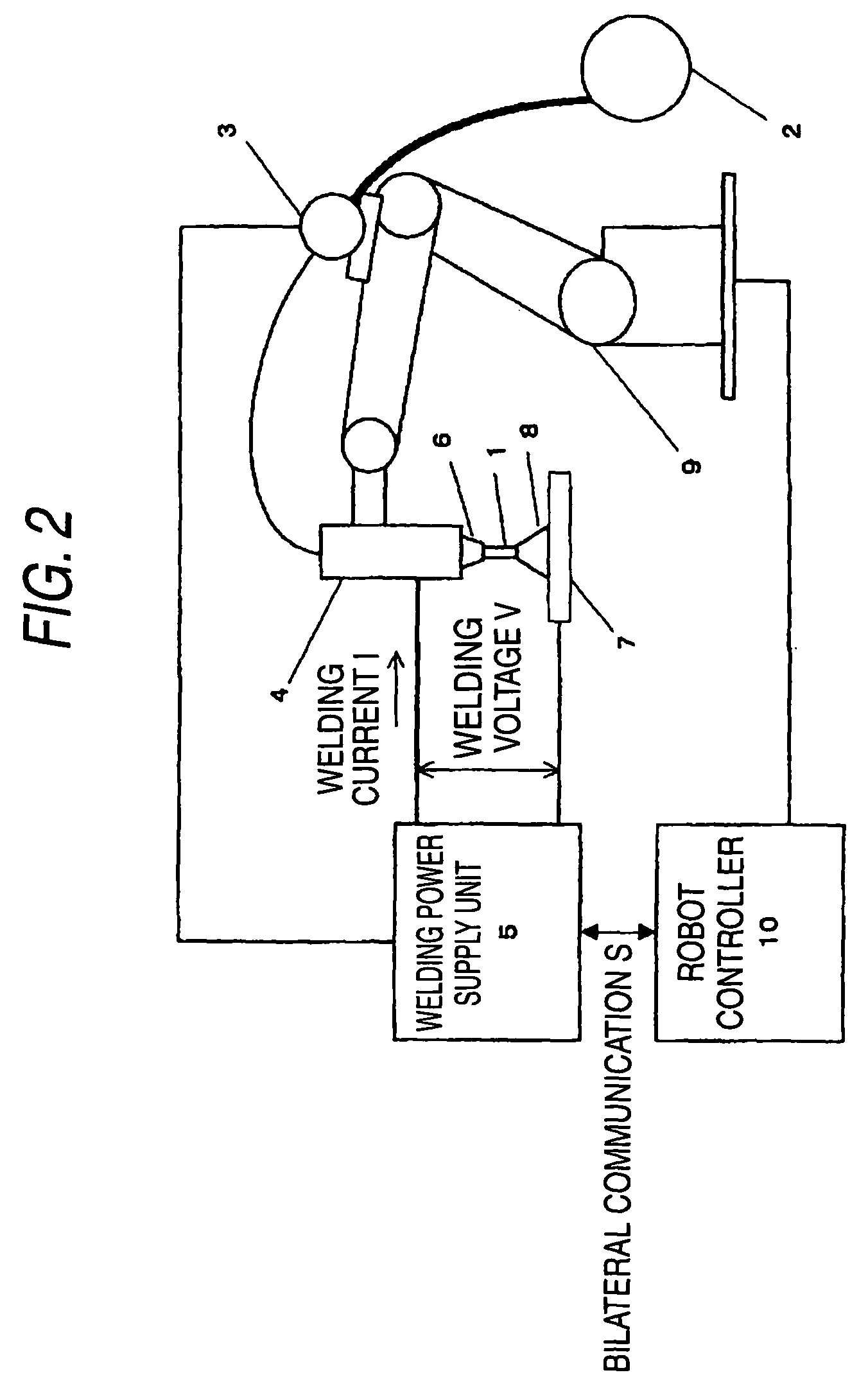
[0137]One embodiment of the invention will be described below with reference to FIGS. 1 to 3 and FIGS. 7 and 8.

[0138]Referring first to FIGS. 2 and 3, construction of a welding system in this embodiment and a process of arc start will be described. Referring next to FIGS. 1, 7 and 8, a position control loop of a robot controller 10 in the embodiment will be described.

[0139]FIG. 2 is a constitutional diagram showing an outline of a welding system in the embodiment. A welding wire 1 that is a consumable electrode is supplied from a wire spool 2 in a direction of a welding torch 4 by a wire feeding motor 3.

[0140]A welding power supply unit 5 applies the predetermined welding current I and welding voltage V between the welding wire 1 and a base material 7 that is a workpiece through the welding torch 4 and a welding tip 6 thereby to generate an arc 8, and controls the wire feeding motor 3 to perform welding.

[0141]A robot manipulator 9, holding the welding torch 4, locates it in a weld s...


PUM

PropertyMeasurementUnit
Rgaaaaaaaaaa
frequencyaaaaaaaaaa
velocityaaaaaaaaaa

Abstract

A torch is moved by a manipulator in a direction separating from a base material 7 while a wire is supplied, whereby an actuator driving the robot manipulator can control a velocity of the wire for a workpiece by a unidirectional operation of separating the torch, and vibration due to reverse of torch velocity is not generated. Further, by using a dedicated separation control system, velocity follow-up performance of the actuator moving the torch can be heightened without increasing overshoot in the usual operation time, and the acceleration and deceleration time of the manipulator can be reduced.

Description

TECHNICAL FIELD[0001]The present invention relates to a control method of controlling a position of a welding robot driven by a motorBACKGROUND ART[0002]Recently, in the industry of welding, more effort into improvement of productivity is continued every day. Particularly, requests to reduce a short-time stop of a production line caused by minor troubles and to reduce a tact time become higher than before.[0003]Various factors are thought as causes of the stop of the production line. The largest cause is a trouble caused by poor arc start.[0004]Therefore, in the arc start in a conventional consumable electrode type welding process, when a start signal is input from the exterior part, a robot manipulator is driven to move a welding torch to a weld-start-position which has been previously taught. Thereafter, in a state where feeding of a wire is stopped, the welding torch is moved by the robot manipulator nearly in the feeding direction of the welding wire and a leading end of the wir...

Claims


Application Information

Patent Timeline
Patent Type & Authority Patents(United States)
IPC IPC(8): B23K9/10B23K9/06
CPCB23K9/0671B23K9/125B23K9/126
Inventor NAKATA, HIROYUKIMUKAI, YASUSHIIKEDA, TATSUYAMASUNAGA, NAOTOKOWA, MASARUHONUCHI, YASUYOSHI
Owner PANASONIC CORP
Learn More