Asymmetric field effect transistor structure and method

a field effect transistor and asymmetric technology, applied in the field of field effect transistors, can solve the problems of increasing circuit delay, gate to drain capacitance can influence circuit delay significantly more, and circuit delay is more sensitive, so as to achieve minimal circuit delay, improve drive current, and improve performance

Inactive Publication Date: 2010-11-30
GLOBALFOUNDRIES U S INC
View PDF9 Cites 16 Cited by
  • Summary
  • Abstract
  • Description
  • Claims
  • Application Information

AI Technical Summary

Benefits of technology

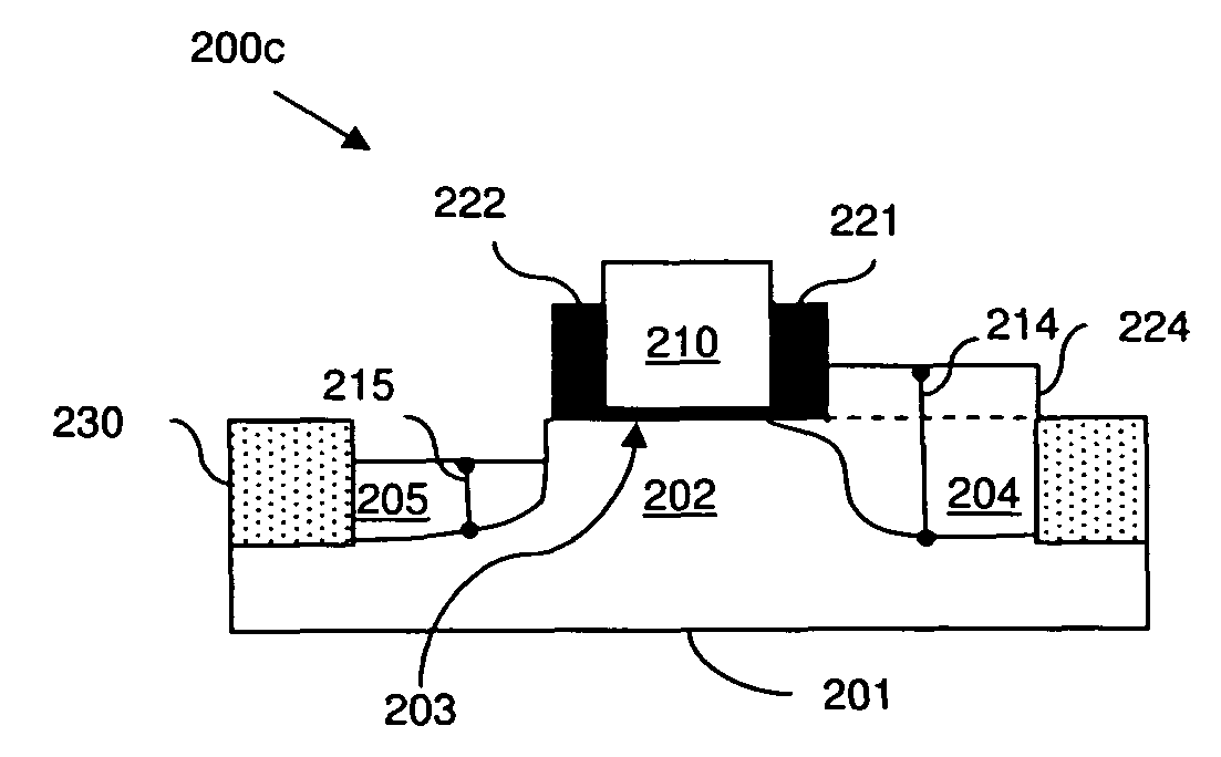
[0011]In this embodiment, in addition to having different heights, the source and drain regions of the transistor structure can further be separated from the gate electrode by different distances in order to further minimize series resistance in the source region as well as to further minimize gate to drain capacitance. Specifically, the source region can have one height relative to the top surface of the channel region and the drain region can have a different lesser height relative to the top surface of the channel region. Additionally, the source region can be separated from the gate electrode by one distance and the drain region can be separated from the gate electrode by a different greater distance. This asymmetric configuration allows for additional tailoring of the series resistance and gate to drain capacitance (i.e., allows for even greater simultaneous minimization of series resistance in the source region and gate to drain capacitance) over asymmetric source and drain heights alone. More specifically, the values of the height of the source region, the height of the drain region, the distance between the source and gate and the distance between the drain and gate can be tailored to ensure that series resistance in the source region is less than a predetermined resistance value and to simultaneously ensure that gate to drain capacitance is less than a predetermined capacitance value.
[0013]Separation of the source and drain regions from the gate electrode by different predetermined distances can, for example, be accomplished by means of gate sidewall spacers having different predetermined widths. That is, the transistor structure can further comprise a sidewall spacer adjacent to the source-side of the gate electrode. This source-side sidewall spacer can comprise a nitride sidewall spacer having a predetermined width that is approximately equal to the desired distance between the source region and the source-side of the gate electrode. The transistor structure can also further comprise another sidewall spacer adjacent to the drain-side of the gate electrode. This drain-side sidewall spacer can similarly comprise a nitride sidewall spacer. However, the predetermined width of the drain-side sidewall spacer can be greater than that of the source-side sidewall spacer. That is, the drain-side sidewall spacer can be approximately equal to the desired distance between the drain region and the drain-side of the gate electrode. Then, during formation, the gate sidewall spacer widths can be used to effectively control positioning of the source and drain dopants during implantation. Thus, the values of the different heights of the source and drain regions and the different sidewall spacer widths (representing the different distances between the source and drain regions and the gate) can be tailored to ensure that series resistance in the source region is less than a predetermined resistance value and to simultaneously ensure that gate to drain capacitance is less than a predetermined capacitance value.
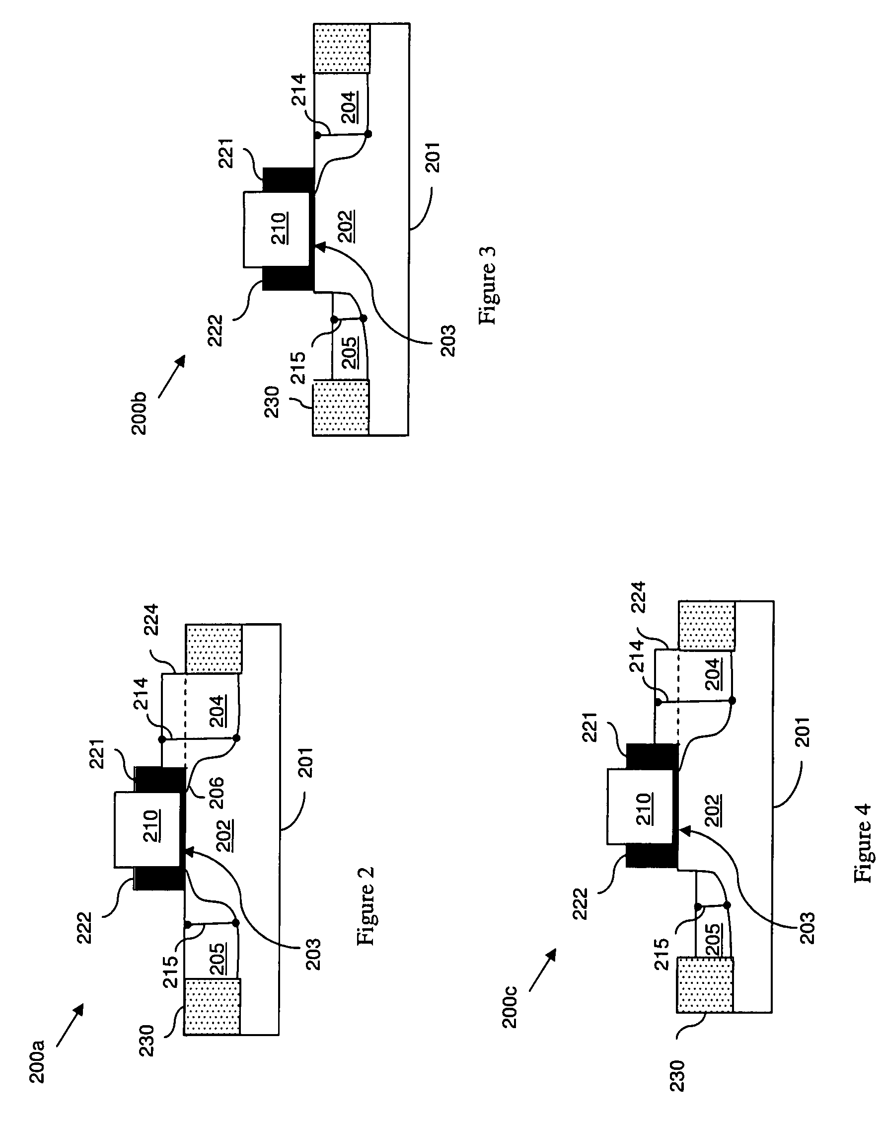
[0015]This method embodiment can further comprise predetermining the height of the source region and the height of the drain region relative to the top surface of the channel region. Specifically, this predetermining process can comprise tailoring the height of the source region and the height of the drain region so that the height of the drain region is less than the height of the source region. This asymmetric configuration allows series resistance in the source region and gate to drain capacitance to be simultaneously minimized. More specifically, the different heights of the source and drain regions can be tailored so that series resistance in the source region is less than a predetermined resistance value and so that gate to drain capacitance is less than a predetermined capacitance value.
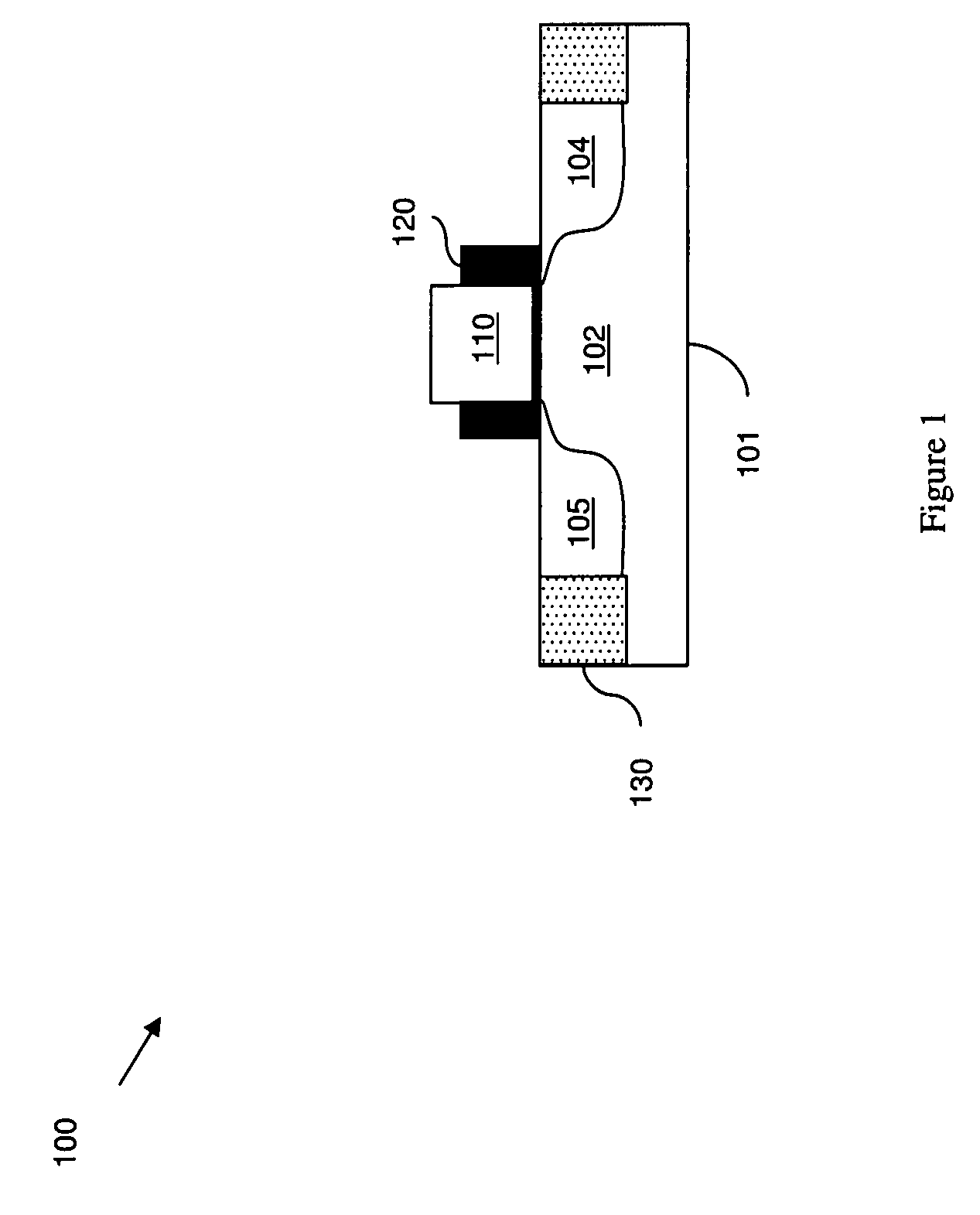
[0019]It should be noted that, during the deep source and drain implant processes, the widths of the gate sidewall spacers control the positioning of the deep source region and deep drain region, relative to the gate electrode. In this embodiment, the gate sidewall spacers are formed symmetrically. Thus, the source and drain regions will be separated from the gate electrode by the same distance (i.e., by a distance that is approximately equal to the sidewall spacer width).
[0021]This method embodiment further comprises predetermining not only different heights for the source and drain regions relative to the top surface of the channel region, but also predetermining different distances between the source and drain regions and the gate electrode in order to simultaneously minimize series resistance in the source region and gate to drain capacitance. That is, this method embodiment comprises predetermining each of the following: the height of the source region, the height of the drain region, the distance between the source region and one side of the gate electrode, and the distance between the drain region and the opposite side of the gate electrode. The heights of the source and drain regions are predetermined relative to the top surface of the channel region. Specifically, this predetermining process can comprise tailoring the different heights of the source and drain regions and the different distances between the source and drain regions and the gate so that the height of the drain region is less than the height of the source region and also so that the distance between the drain region and the gate is greater than the distance between the source region and the gate. This asymmetric configuration allows for additional tailoring of the series resistance and gate to drain capacitance (i.e., allows for even greater simultaneous minimization of series resistance in the source region and gate to drain capacitance) over the transistor configurations with asymmetric source and drain heights alone. More specifically, the different predetermined heights and different predetermined distances can be tailored so that series resistance in the source region is less than a predetermined resistance value and so that gate to drain capacitance is less than a predetermined capacitance value.

Problems solved by technology

Additionally, circuit delay is more sensitive to gate to drain capacitance than gate to source capacitance.
That is, due to the Miller effect, the gate to drain capacitance can impact circuit delay significantly more than gate to source capacitance.
However, techniques associated with reducing source / drain resistance to improve drive current often simultaneously increase the gate to drain capacitance, thereby increasing circuit delay.
Similarly, techniques associated with reducing gate to source / drain capacitance often simultaneously increase source resistance, thereby degrading drive current.

Method used


Image

  • Asymmetric field effect transistor structure and method
  • Asymmetric field effect transistor structure and method
  • Asymmetric field effect transistor structure and method

Examples


embodiment 200

[0059]In this embodiment 200, the source and drain regions 204, 205 can have different heights 214, 215 that are tailored to minimize series resistance in the source region as well as to simultaneously minimize gate to drain capacitance. Specifically, the source region 204 can have one height 214 (i.e., a first predetermined height) relative to the top surface 203 of the channel region 202 and the drain region 205 can have a different height 215 (i.e., a second predetermined height) relative to the top surface 203 of the channel region 202. The predetermined height 215 of the drain region 205 can be less than the predetermined height 214 of the source region 204 (i.e., the height of the drain region can be lower relative to the top surface of the channel region than the height of the source region). This asymmetric configuration allows series resistance in the source region and gate to drain capacitance to be simultaneously minimized. More specifically, the values of the height 214 ...

embodiment 300

[0065]In this embodiment 300, in addition to having different heights 314, 315, the source and drain regions 304, 305 of the transistor structure 300 can further be separated from the gate electrode 310 by different distances 351, 352 in order to further minimize series resistance in the source region as well as to further minimize gate to drain capacitance. Specifically, the source region 304 can have one height 314 (i.e., a first predetermined height) relative to the top surface 303 of the channel region 302 and the drain region 305 can have a different lesser height (i.e., a second predetermined height) relative to the top surface 303 of the channel region 302. That is, the height of the drain region can be lower, relative to the top surface of the channel region, than the height of the source region. Additionally, the source region 304 can be separated from the gate electrode 310 by one distance 351 (i.e., a first predetermined distance) and the drain region 305 can be separated...


PUM


Abstract

Disclosed are embodiments for a design structure of an asymmetric field effect transistor structure and a method of forming the structure in which both series resistance in the source region (Rs) and gate to drain capacitance (Cgd) are reduced in order to provide optimal performance (i.e., to provide improved drive current with minimal circuit delay). Specifically, different heights of the source and drain regions and / or different distances between the source and drain regions and the gate are tailored to minimize series resistance in the source region (i.e., in order to ensure that series resistance is less than a predetermined resistance value) and in order to simultaneously to minimize gate to drain capacitance (i.e., in order to simultaneously ensure that gate to drain capacitance is less than a predetermined capacitance value).

Description

CROSS-REFERENCE TO RELATED APPLICATIONS[0001]This application is related to a Continuation In Part of U.S. application Ser. No. 11 / 778,185 filed Jul. 16, 2007, the complete disclosure of which, in its entirety, is herein incorporated by reference.BACKGROUND[0002]1. Field of the Invention[0003]The embodiments of the invention generally relate to field effect transistors (FETs) and, more particularly, to an asymmetric FET structure and method of forming the structure that provides minimal resistance in the source region and minimal capacitance between gate and drain region in order to optimize performance.[0004]2. Description of the Related Art[0005]In conventional symmetric planar metal oxide semiconductor field effect transistors (MOSFETs), there is an intrinsic trade-off between source / drain series resistance and gate to source / drain capacitance. Specifically, FET saturated currents are more sensitive to source resistance and less sensitive to drain resistance. That is, FET drive c...

Claims


Application Information

Patent Timeline
Patent Type & Authority Patents(United States)
IPC IPC(8): H01L29/78
CPCH01L29/0847H01L29/665H01L29/66628H01L29/66636H01L29/66659H01L29/78H01L29/7834H01L29/7835
Inventor ANDERSON, BRENT A.BRYANT, ANDRESCLARK, JR., WILLIAM F.NOWAK, EDWARD J.
Owner GLOBALFOUNDRIES U S INC
Why Eureka
Try Eureka