Module for electrical energy storage assemblies having a flat connecting strip

a technology of electrical energy storage and modules, applied in the direction of cell components, final product manufacturing, sustainable manufacturing/processing, etc., can solve the problems of premature wear of storage assemblies, substantial production costs, and difficulty in managing cooling of such modules

Inactive Publication Date: 2015-02-24
BLUE SOLUTIONS
View PDF12 Cites 2 Cited by
  • Summary
  • Abstract
  • Description
  • Claims
  • Application Information

AI Technical Summary

Benefits of technology

[0017]So the presence of welding beads and the absence of circular overlapping edges on the peripheries of the faces of the covers combined with use of planar binding strips reduce production costs of the modules. This combination also maximises the contact surface between the strip and the covers on the one hand, minimising series resistance Rs, and between the strip and the cowling (with or without intermediate material) on the other hand, making it easier for thermal exchanges between the interior and exterior of the module.

Problems solved by technology

These two electric connection means on the one hand require tight tolerances of the terminals and strips and on the other hand precise mutual alignment of the pieces to finally ensure production of a quality module, resulting in substantial production costs.
This causes difficulties in managing cooling of such a module.
This causes difficulties in thermal evacuation, in controlling series resistance, premature wear of the storage assemblies.
Another disadvantage of these three types of operation is the difficulty in producing modules where the elements are correctly aligned, and where the strips are parallel to the surface of the covers.

Method used


Image

  • Module for electrical energy storage assemblies having a flat connecting strip
  • Module for electrical energy storage assemblies having a flat connecting strip
  • Module for electrical energy storage assemblies having a flat connecting strip

Examples


Embodiment Construction

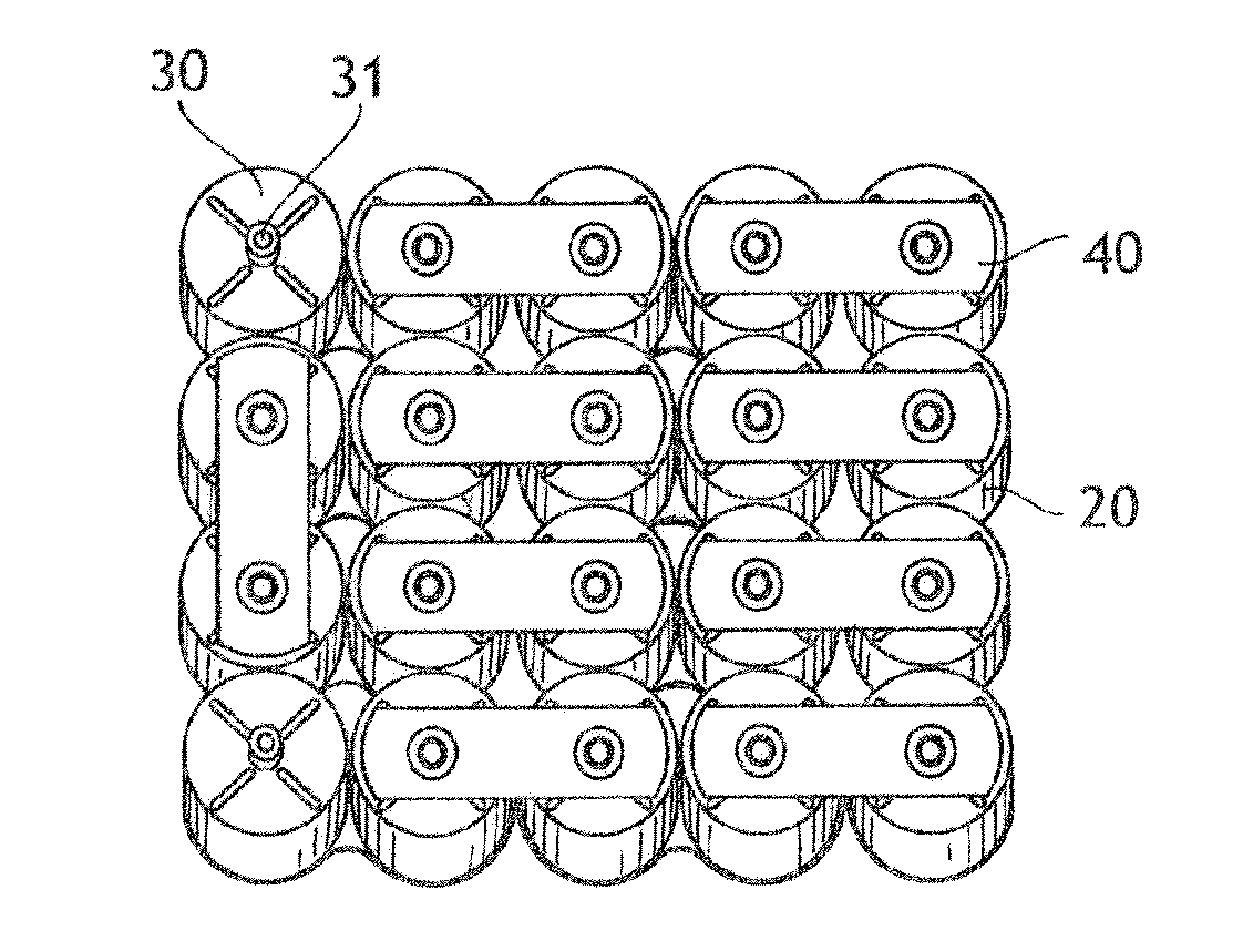
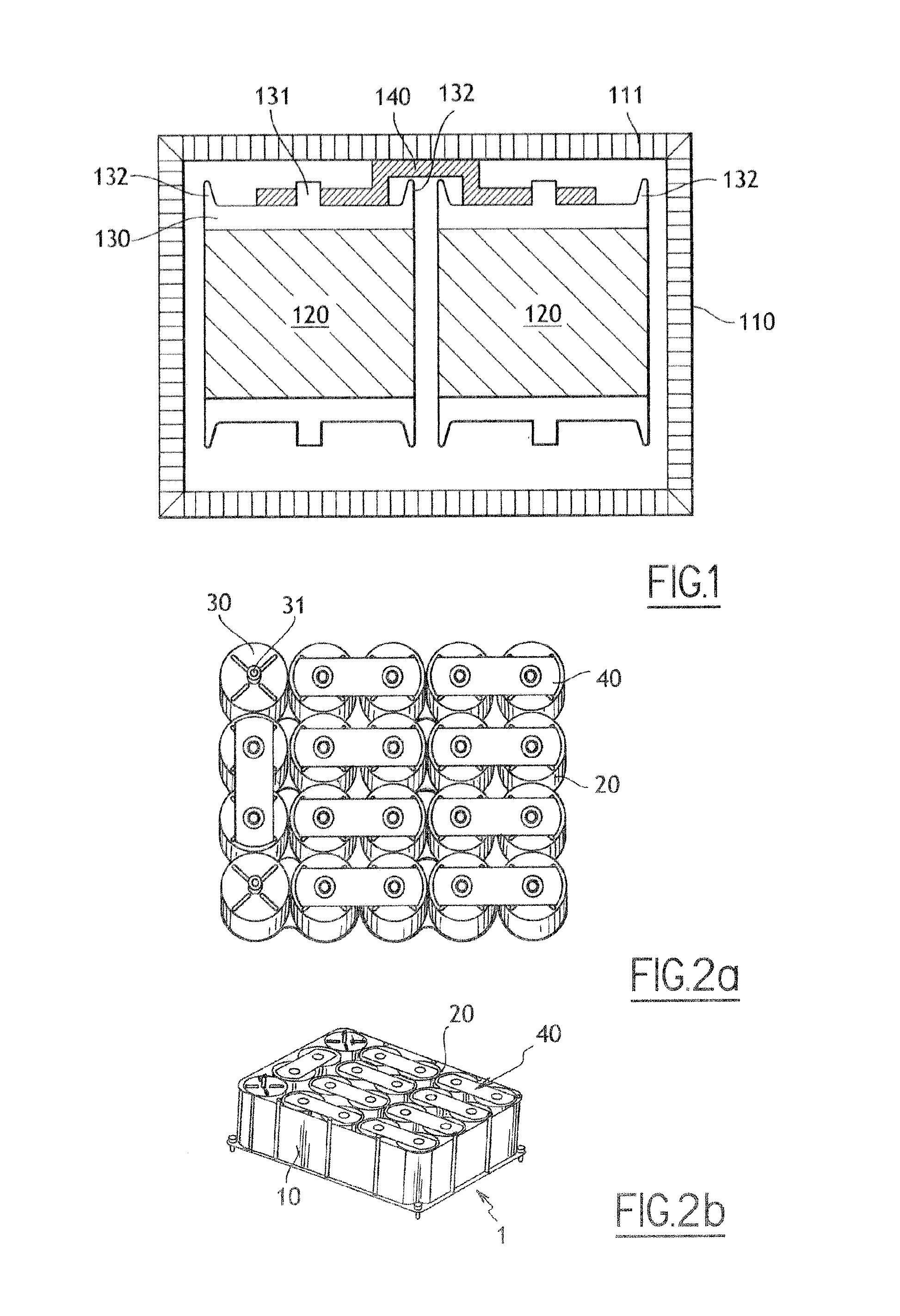
[0058]Different embodiments of the module according to the invention will now be described in reference to the figures. In these different figures, the equivalent elements of the module bear the same reference numerals. As illustrated in FIG. 2b, the module 1 comprises a casing 10 in which at least two electric energy storage assemblies 20 are arranged.

[0059]The storage assemblies 20 have an overall cylindrical shape. The storage assemblies 20 are arranged side by side in the casing 10. In other terms, the axes of revolution of the storage assemblies 20 are parallel. In the embodiment illustrated in FIGS. 2a and 2b, the storage assemblies 20 are arranged so that their axes of revolution are perpendicular to the lower wall of the casing 10. In other variants not shown here, the storage assemblies can be parallelepiped, square, oval, hexagonal in shape, without this changing the general principles of the invention.

[0060]Each storage assembly 20 comprises a first face topped by a cover...


PUM

PropertyMeasurementUnit
thermal dissipationaaaaaaaaaa
distanceaaaaaaaaaa
electricaaaaaaaaaa

Abstract

The invention relates to a module comprising at least two electrical energy storage assemblies (20), each storage assembly (20) comprising a first face topped by a cover (30) electrically connected to said energy storage assembly (20) and a second face opposite the first face, each cover being in contact with a respective end of a strip (40) in order to electrically connect the two storage assemblies (20), in which the strip (40) and the faces of the covers (30) in contact with the strip (40) are flat, the strip (40) being welded to the faces of the covers (30) along weld leads (50, 50′).

Description

[0001]This is a non-provisional application claiming the benefit of International application number PCT / EP2008 / 062129 filed Sep. 12, 2008[0002]The present invention relates to the general technical field of electric energy storage assemblies.[0003]More particularly the invention relates to the field of modules comprising at least two electric energy storage assemblies.[0004]Within the scope of the present invention “electric energy storage assembly” is understood to mean either a condenser (i.e. a passive system comprising two electrodes and an insulator), or a supercondenser (i.e. a system comprising at least two electrodes, an electrolyte and at least one separator), or a battery of lithium battery type (i.e. a system comprising an anode, a cathode and an electrolyte solution between the anode and the cathode).GENERAL PRESENTATION OF PRIOR ART[0005]Modules such as illustrated in FIG. 1 are known, comprising a casing 110 in which several electric energy storage assemblies 120 conn...

Claims


Application Information

Patent Timeline
Patent Type & Authority Patents(United States)
IPC IPC(8): H01M2/24H01G9/00H01G4/38H01M6/42H01M50/529H01G9/04H01G15/00H01M50/503H01M50/516H01M50/522
CPCH01M2/0426H01G9/058H01M2/1094H01M2/204Y02E60/13H01G11/10H01G11/76H01G11/82Y02E60/10H01M50/169H01M50/24Y02P70/50H01M50/522H01M50/516H01M50/503H01G11/22
Inventor CAUMONT, OLIVIERDEPOND, JEAN-MICHELJUVENTIN, ANNE-CLAIRE
Owner BLUE SOLUTIONS
Why Eureka
Try Eureka