
Micromirror system

a micromirror and mirror technology, applied in the field of micromirror systems, can solve the problems of cardanic suspension, relatively complicated design and actuation, and respect to the dynamic properties of the micromirror, and achieve the effect of reducing the electric effective distance between the electrodes and the assigned mirror

Inactive Publication Date: 2010-11-30
ROBERT BOSCH GMBH
View PDF2 Cites 3 Cited by
  • Summary
  • Abstract
  • Description
  • Claims
  • Application Information

AI Technical Summary

Benefits of technology

The present invention provides an improved micromirror system that can deflect an optical beam in two directions perpendicular to each other. The micromirrors are patterned out of a substrate wafer, eliminating the need for complicated adjustment. The micromirrors are damped using a gas medium or fixed and / or movable structures. The invention also includes electrodes tilted towards the mirrors, which reduces the required electric voltage and allows for unrestricted rotation of the mirror.

Problems solved by technology

However, the cardanic suspension has the disadvantage that it is relatively complicated in design and actuation, and in addition, also has disadvantages with respect to the dynamic properties of the micromirror.
However, this has the disadvantage that the optical adjustment of the mirrors in the optical path is relatively complicated.
For example, an imprecise mounting results if the micromirrors are only inserted or put on.

Method used


Image

  • Micromirror system
  • Micromirror system
  • Micromirror system

Examples


Embodiment Construction

[0016]Hereinafter in the different specific embodiments of the invention, essentially identical or similar parts are provided with the same reference numerals.

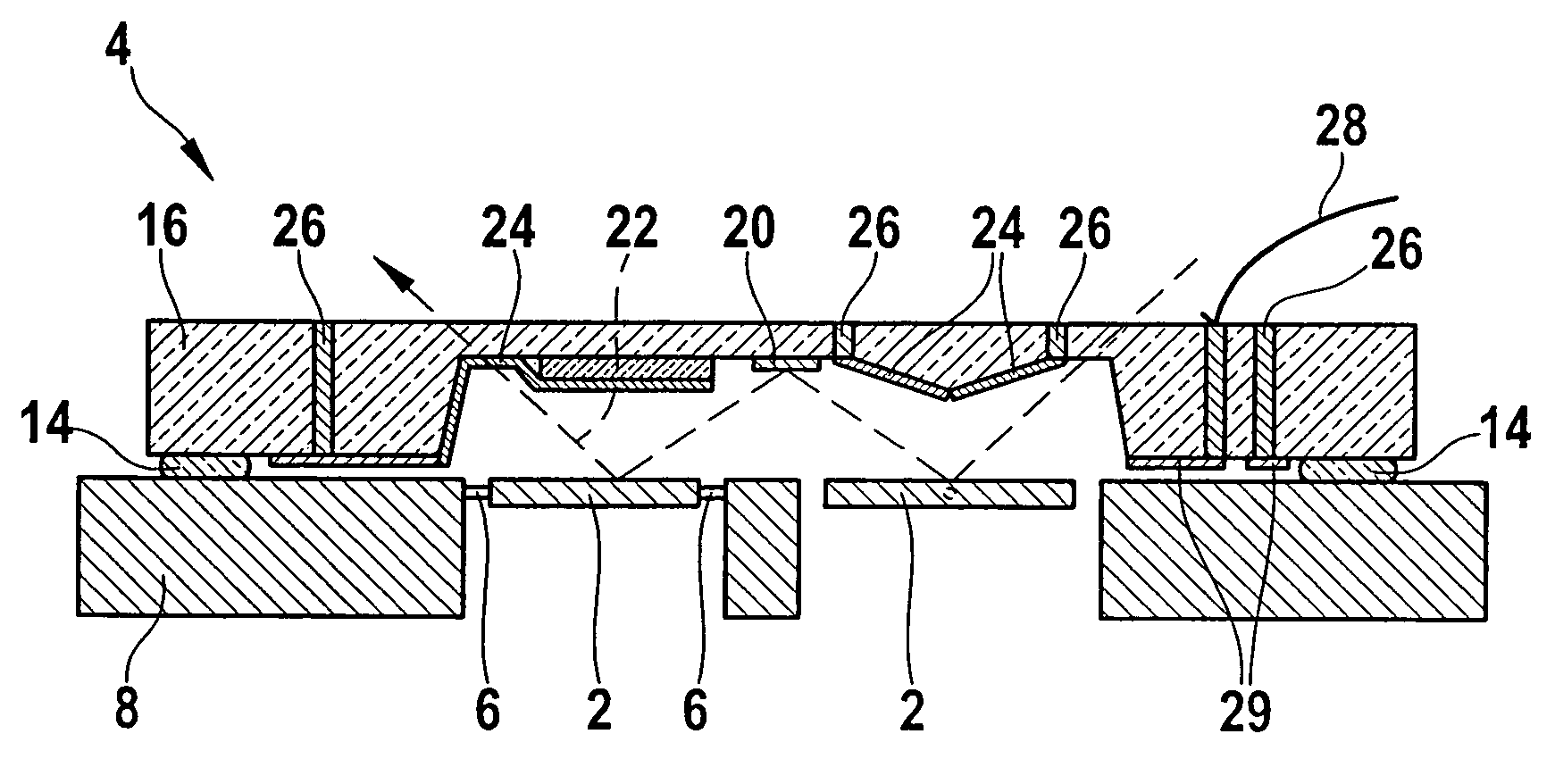
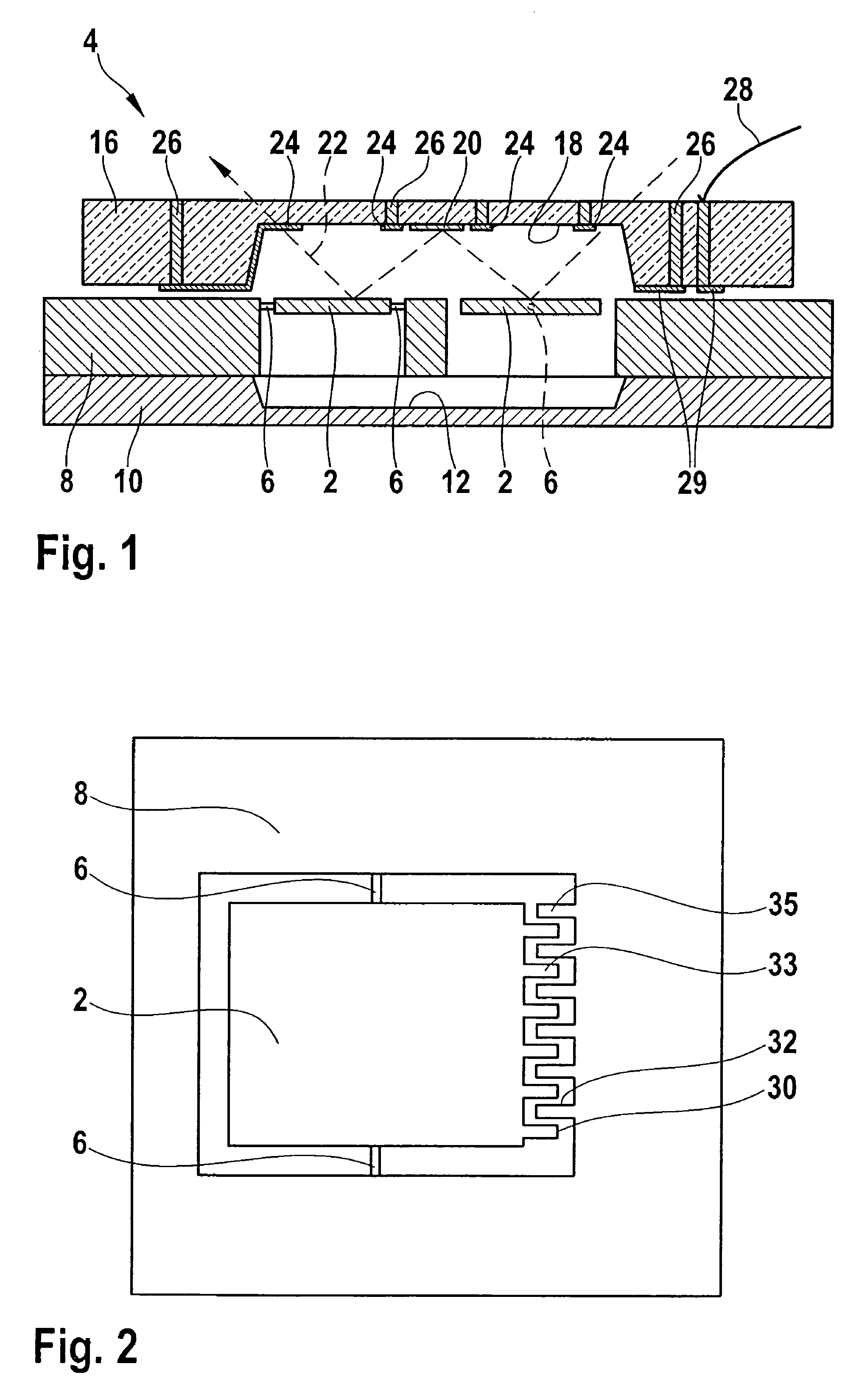
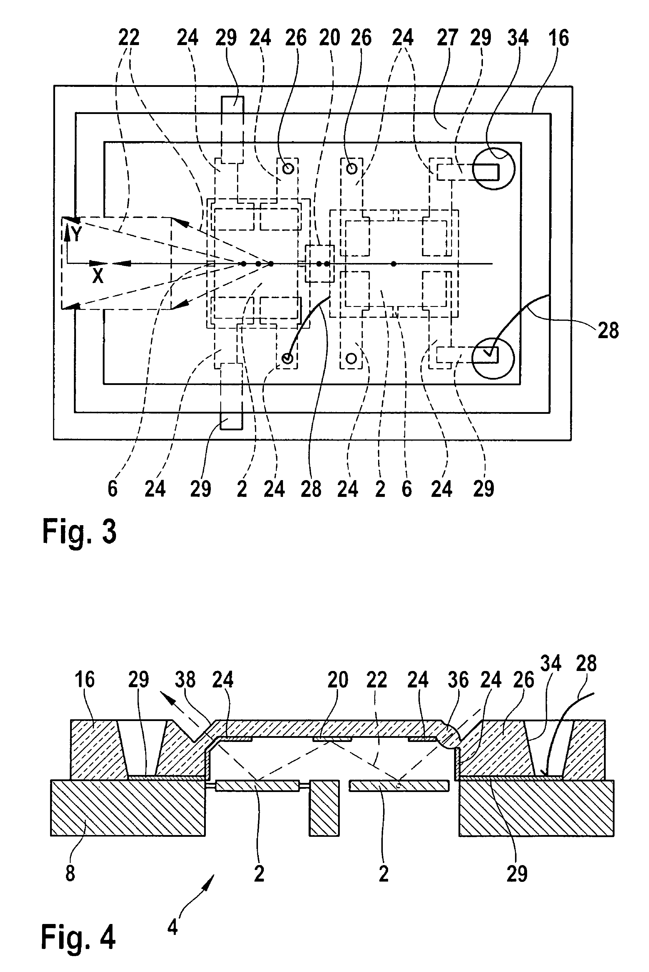
[0017]In the first specific embodiment as shown in a cross-sectional view in FIG. 1, a micromirror system 4 is made up, for example, of at least two micromirrors 2. Micromirrors 2 in each case are suspended on two opposite sides centrally or along one of their axes of symmetry, on torsion springs 6. Preferably, torsion springs 6 of the two micromirrors 2 are disposed essentially perpendicular to each other, as shown in the top view in FIG. 3. Besides the planar, quadrangular shape shown in FIGS. 1 and 2, micromirrors 2 may have any planar shape as desired, for example, a circular, oval or multi-angular shape, or perhaps a curved shape, for instance, in the form of an imaging concave mirror.

[0018]Micromirrors 2 are patterned or etched out of a substrate wafer 8. In so doing, micromirrors 2 may be produced, for instance, by anis...


PUM


Abstract

A micromirror system having at least two micromirrors, each suspended on a substrate wafer via at least one torsion spring. The axes of rotation of the micromirrors are disposed essentially perpendicular to each other in order to permit deflection of an optical beam in two directions essentially perpendicular to each other. The micromirrors and the torsion springs are patterned out of the substrate wafer and lie essentially in one plane.

Description

FIELD OF THE INVENTION[0001]The present invention relates to a micromirror system, for the deflection of an optical beam, which can be used in head-up displays, projectors or scanners.BACKGROUND INFORMATION[0002]Micromirrors are described in the related art which have two axes of rotation that are perpendicular to each other, so that light can be deflected not only in one plane, but in two planes. For example, presently such micromirrors are contemplated for head-up displays in the automotive sector, but also for other applications such as image projectors and 2-D scanners.[0003]To permit the mobility of a micromirror in two planes, the micromirror is usually doubly suspended cardanically on torsion springs. In so doing, for example, the micromirror may be surrounded by an inner cardan frame and joined to this inner cardan frame via a pair of aligned torsion joints. In turn, the inner cardan frame is joined via aligned torsion joints to an outer cardan frame. However, the cardanic s...

Claims


Application Information

Patent Timeline
Patent Type & Authority Patents(United States)
IPC IPC(8): G02B26/08
CPCG02B26/0841
Inventor PINTER, STEFAN
Owner ROBERT BOSCH GMBH
Learn More